Applet: Nora Willett
Text: Marc Levoy
Technical assistance: Andrew Adams
Systems for automatically focusing a photographic camera can be partitioned into two classes: active and passive. In active systems some kind of radiation is sent towards the scene: sonar, laser, structured light, etc. Its reflection from objects in the scene is captured by the camera's main sensor or another sensor and analyzed using triangulation to determine the objects' distance from the camera. In passive systems nothing is sent towards the scene. Instead, the scene is captured under its own ambient illumination, and this image is analyzed to determine distance. In some passive systems the camera may provide additional illumination during focusing, sometimes called an autofocus assist light. This is particularly useful if the scene is dark. In other systems the camera may project a grid or texture onto the scene to aid with the analysis. This is useful when focusing on textureless surfaces. In either case, if the position and direction of the illumination is unknown, then by convention the system is still called passive. In this applet and the succeeding one, we consider the two most common types of passive autofocus systems: phase detection and contrast detection.
|
|
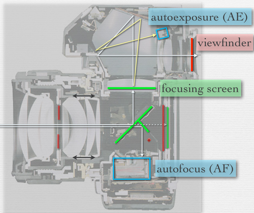
Phase detection is the most common type of passive autofocus method used in single-lens reflex (SLR) cameras. The cross-section image at left represents the Nikon F4, an early, film-based SLR with autofocus. During aiming and focusing the light path from lens to sensor (dashed white line) is intercepted by the reflex mirror (large green line at a 45-degree angle), which reflects it up to the focusing screen (horizontal green line) and from there to the viewfinder. (For more information on these, see slides 6 through 8 of the lecture titled "Autofocus (AF)".) However, the reflex mirror contains a partially silvered section. This allows a portion of the light to pass through it to a smaller, secondary mirror, which reflects the light down to the autofocus module. In the applet above, we show only this secondary mirror. |
Inside the autofocus module (blue rectangle on the cross-section image above) there are two or more small image sensors, each one having a microlens above it. These sensors are typically one-dimensional, i.e. a row of pixels, and they come in pairs. Each pair constitutes one autofocus point (AF point), which looks at one part of the camera's field of view. A modern SLR may have many dozens of autofocus points, implemented as sensor tiles crammed onto a single chip. In the applet we show the sensors and microlenses of one AF point, which is looking at the center of our simulated camera's field of view. The blurry image at the bottom of the applet represents the image seen through this camera's viewfinder, and the tiny white rectangle represents the position of our AF point - at the image's center. If you follow the red bundle of rays in the applet, they start (at left) in the scene, pass through the top of the main lens, and are focused by Micro Lens 1 onto CCD 1. This CCD therefore sees a snippet of whatever feature lies at the center of the camera's field of view, but as viewed from the top edge of the camera's aperture. The green bundle of rays sees the same feature, but as viewed from the bottom edge of the camera's aperture. Since these two edges are separated by some distance (even if only a few millimeters), they will see slightly different views.
Use the slider to move the lens left and right. As you do so the intersection at the right side of the applet of the (weakly drawn) red and green bundles moves correspondingly. While these rays are currently blocked by the mirror, the applet shows where they would intersect if the mirror were flipped out of the way. Note that they don't intersect at the sensor. This means that this scene feature is misfocused. We represent this misfocus by the blurry image in the simulated viewfinder at the bottom of the applet. Now look where the ray bundles land on CCD 1 and CCD 2. As you move the lens, these landing points shift left or right. At the bottom of the applet is a plot in red of what CCD 1 sees and a superimposed plot in green of what CCD 2 sees. Although the simulated viewfinder shows a coin, we simplify these plots by assuming for them that the camera is looking at a single bright point on a black background, Under this assumption the plots consist of two peaks, one for each CCD.
By playing with the slider, it should become clear that the distance between the red and green peaks on the plot is related to the angles the red and green bundles make with the optical axis (horizontal black line) when they arrive at the lens from the scene. Move the slider until the two peaks coincide. When they do, the red and green bundles are now both aimed at the bright point assumed to be in the scene. If you flip the mirror out of the way, their image is now well focused on the sensor. Note also that the simulated image of a coin at bottom of the applet is now sharp.
Given this geometry, how does autofocusing proceed? First, the one-dimensional images falling on these two CCDs are captured and read off the chip. They are then analyzed digitally using a small embedded processor to estimate how much one image is shifted with respect to the other. It's beyond the scope of this applet to describe the many ways of performing this estimation; cross-correlation is one such method. In our trivial example the shift we seek is equal to the distance between the red and green peaks, which we can see at a glance from the plot. Once this shift is known, the system knows how far to move the lens to make the two images align. It can therefore instruct the lens to move directly to the correct position, without taking a second measurement or "hunting" around. In practice it usually moves close to the correct position, then takes additional measurements to refine this position.
The ability to move directly to the in-focus position makes phase detection a fast autofocus method, faster at least than contrast detection. Unfortunately, this method can only be used when the reflex mirror is down. Thus, in Live preview mode (called "Live View" on Canon cameras), in which the mirror is flipped up, the camera cannot use phase detection. In this mode the camera either offers no autofocusing at all or it offers only contrast detection, which we consider in the next applet.
A common task in computer vision algorithms is to track the motion of an object as it moves across the screen. Equivalently, one might track the motion of the camera as it moves in front of the scene. In both cases, the algorithm is trying to determine the phase (i.e. placement) of the object relative to the field of view of the camera. This is the same task performed by phase detection autofocusing. In fact, computer vision algorithms could perform this task with the help of the optics we've discussed here.
A similar idea arises in the study of the light field - the set of all positions and directions of light rays traveling through space. One method we've used in our laboratory for recording light fields is to place a microlens array in the optical train of a camera or microscope. From the resulting data we can track the motion of objects, just as we've done on this web page with only two microlenses. Astronomers use arrays of microlenses in a similar way, to track the twinkling of stars seen through their telescopes. This tells them about perturbations to their view caused by atmospheric turbulance. They call this tracking and correction task adaptive optics, and they call the array of microlenses a Shack-Hartmann wavefront sensor.
One more sidelight. Here's an iPhone app called SynthCam - available in the iTunes app store - which combines the notion of tracking a camera's motion to determine phase, with focusing based on that phase information. The goal of the app is to approximate images taken with a larger aperture (i.e. a synthetic aperture) than that of the cell phone camera. Images made with such an aperture will have a shallow depth of field. If you don't own an iPhone, here's a web site with examples of photographs created using the app.