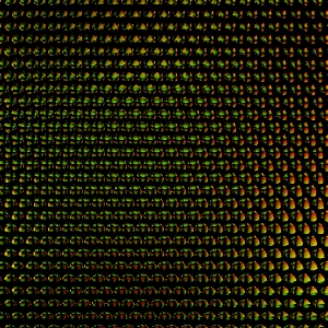
Figure 1: A close up of a lenticular lens system.
The purpose of this assignment is to add some new lens types to lrt that support 3D photography. Specifically, you will be adding a lenticular lens and a "flyseye" type lens. When you are done with this assignment, you'll be able to print out an image generated by lrt, place a real version of your simulated lens over the image, and have a 3D picture!
To specify a lenticular system you should change the Projection line in your rib file to
Projection "lenticular" "radius" rad "pitch" pit "fov" fov
To specify a flyseye system you should change the Projection line in your rib file to
Projection "flyseye" "radius" rad "pitch" pit "fov" fov
ScreenWindow xmin xmax ymin ymaxThe default (if unspecified) is
ScreenWindow -4.3 -1 4.3 1and results in a 640x480 image of aspect ratio 4/3. If you change the default image size (ie Format 200 200 1), the screen window and aspect ratio change appropriately.
We can assume the lens system is large enough to cover the screen coordinate space. The combination of specifying an image size (say 200 by 200 pixels) and the ScreenWindow (say the default) tells us how many pixels are covered by each lens element. You will have to set the screen window appropriately to get a desired number of pixels per lens element. Be careful when you do this, however. When you change your ScreenWindow parameter, keep the aspect ratio the same as your specified image aspect ratio, or you'll get weird results.
As a concrete example, if you have 100 flyseye lens elements covering the film plane (with ScreenWindow at the default setting of -1 1 -1 1) for a 100x100 image, you get 100 pixels per lens element. Changing the ScreenWindow to 0.5 1 0.5 1 will give you 25 lens elements over a 100x100 image, or 400 pixels per lens element.
We will be giving out specifications for the size of the lenses we will be using, and the targeted number of pixels per lens element. The images you generate should be correct for these parameters.
Notice from figure 3 that some rays will hit neighboring lens elements. We won't have to trace these rays, as they will never be seen. The fov parameter can be used to calculate r < R (radius), which is the point where the rays bend into neighboring cells and don't need to be traced. The rays bend out from the lens as the normal at that point on the lens.
The stubs in projections.cc pass your routine all the information specified in the rib file for the projection, plus a film plane sample point in RasterCoordinates. The film plane is the z=0 plane. You'll want to take the given film point, translate it (in z) up to the lens, and fire the ray off in the direction of the surface normal to that point. There's a lot of coordinate systms here, so make sure you are working in a consistent frame of reference, and return the ray in the correct frame. We may change the direction function to match the real lenses we get, so make your code modular.
We need some conventions for placing the lens system on the film plane. For this assignment, assume that there is a lens element centered at (0,0) in SWC. For the lenticular lens system, the cylinders will be oriented vertically.
Part of this assignment is digging into the workings of lrt and figuring out how it works. Looking at camera.cc and learning how it generates orthographic and perspective rays will be helpful. This is a real world excercise: You're given a bunch of code and asked to extend its functionality.
This assignment takes a lot of pre-coding-thinking to get a handle on what is going on and what you need to do. Be sure to read this page several times to try and get a handle on what is going on, and try drawing the process out on paper. Once you understand the conceptual picture, the implementation won't sound nearly as bad as it likely does right now.
Sometime before the assignment is due, we'll be giving you the specifics of the lens systems we've got so you can produce images that, when printed, will be 3D. Details are forthcoming.
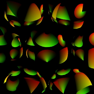
Flyseye view of small.rib. I've provided this to
help show what happens with the lenses. These lenses are huge compared to
the ones above.
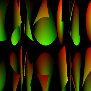
Lastly, a lenticular view of the same small.rib file. To get
this, just modify small.rib by adding the following line:
Projection "lenticular" "radius" .5 "pitch" 1 "fov" 180.0Be sure to coment out your flyseye projection.
The images aren't the best, but it gives you an idea of what to expect from the lens systems when applied to everyone's favorite input rib file - modified slightly. They are not meant to serve as exhaustive tests for your project. Once you can render these correctly, you should be able to generate more tests and determine if your system is working correctly. Note that I'm shooting my rays backwards when they miss a lens element to illustrate the structure of the lens system.
We've finally received some of the lens material to start trying to model correctly. It looks like the correct lens radius is 0.045 and the proper pitch is 0.091932 for flyseye.
This homework is based loosely on Passive Autostereoscopic Light Field Displays done at MIT by Aaron Isaksen and Leonard McMillan.
Copyright © 2000 Pat Hanrahan