Final Writeup
Rendering Cloth by Virtual Goniometry
Project Goal
My goal was to render an image of a piece of cloth which appears as if the full geometry were used (self shadowing, transparency, and anisotropic reflections) when in fact only a flat surface was input. My plan was to sample the light field about a single stich and reuse that information locally for each point on the surface.
Implementation
Geometric Modelling: There were two things to be modelled in this project: the basic stitch, and the cloth surface. For the stitch, there core geometry can be specified one by 5 points each for two lines as shown in the picture:
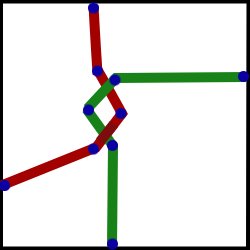
These two threads are approximated by a 5 point spline which is then sampled at a fine resolution to get a dense list of points. Consider the first quarter specified the upper left quarter. The upper right quarter is generated by copying the points from the UL corner and reflecting them across the X = 0 plane. For the lower half of the stitch, copy the upper half and offset it down by 1 unit.
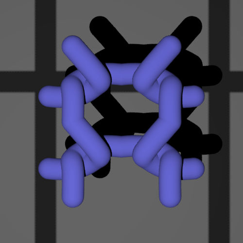
From the spline produced sample points a smooth curved surface is generated by outputting pbrt code for spheres at each point. The code was done so I could change the radius of the spheres and thus the thread with a parameter to try different looks. A value of 7.5% of one unit stich size seemed reasonable graphically. I chose to render with an approximation based on spheres because they are computationally simple to check collisions against compared with the somewhat dense triangle mesh that would have been required to produce a smooth surface.
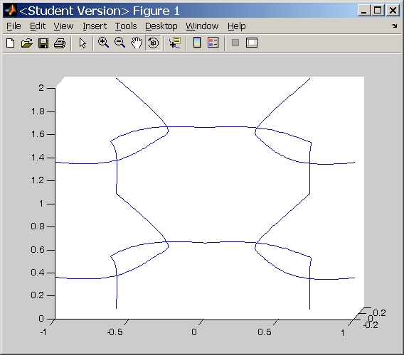
Here is a picture of the path of a unit stich:
When the stitch is rendered in pbrt, here is what it looks like:
There are many meshes on the internet representing various garments and pieces of simulated cloth. All of the first N I tried either had inconsistent half-edges and were therefor incompatible with the PBRT subdivision routine, or they had inconvienent or missing texture coordinates. The final mesh I used was produced by code found at the following site:
http://www.its.caltech.edu/~matthewf/Chatter/Cloth.html
This code worked great for providing an arbitrarily subdivided mesh but required I add in support for texture coordinates.
Sampling
The goal of the sampling phase is to record the amount of light which hits the eye based: where the light hit the stitch (spatial subdivision), the w_i(phi, theta), and wo(phi, theta). The general appoach is to use a new pbrt camera plugin which iterates over a grid of the above parameters and for each combination, a set of rays is cast to represent the integral of irradience on a single pixel representing the center of the camera.
Forward reference: when using the output of the sampling to render something, it is important to be able to lookup w_i and w_o in shading coordinates since thats all we have in pbrt at the time. Shading corrdinates are based off the surface normal and two tangent vectors computed via the DifferentialGeometry. These tangents are mapped to the x and y axis with the normal becoming the z. It became much simpler to work with once I aligned the sample along the z=0 plane with the camera alone the positive z axis in world coords. Also, texture coordinates went from 0,0 in the -x,-y corner up to 1,1 in the +x,+y corner in world space. With this setup, shading coords and world coords were lined up when doing the rendering.
A grid of 9 copies (3x3) of the basic stich was used where only the center stitch was sampled. This was done to simulate the effect of light reflecting off neighboring stiches. Self shadowing and shadowing of one stitch on another will naturally be produced in the reconstructed image this way.
In order to maximize the effectiveness of each pbrt sample, they were cast from anywhere in the source pixel (hard coded to be .01 units square) to a square on the surface of the sample plane whose size depended on number of spatial samples desired. Since this randomness was designed to improve the accuracy of a single sample and the samples were indened to be at fixed angular locations, both the light and the camera were moved VERY FAR away along their rays so angles were the same to 4 decimal places for any place in the sample set. The requires the power of the light be adjusted by the square of the distance it travels. Further, since a point light source was used, the results were scaled by a factor of PI in order to get units in terms of the energy put off by the source light. The final adjustment was to scale by 1/cos(theta) where theta is the angle of the light with the planar surface *not* the angle of the light with the intersection surface. This is because when we lookup values in this table we will be doing so on a planar surface and the fact that less light is reflected from a microscopic surface on the stitch is at a larger theta angle is going to be correctly reconstructed.
The alpha was recorded along with reflected light and was determined by pbrt as: rays which hit things count as alpha = 1 with some weight, rays which hit nothing have alpha = 0 and also some weight--when all is scaled we end up with and alpha < 1.
In order to compute differential rays I added translated a 1 pixel move in X and Y in camera coords into my pixel size of .01 units.
Data Representation
Pbrt has built in support for materials represented with the Lafortune anisotropic reflection model but no built in support for a table based BRDF so initially I planned to treat my samples as points to be fit against a 2-3 lobe Lafortune model. To do this, I structured a non-linear optimization problem where I would minimize the sqared error of the 5 Lafortune terms. A Levenberg-Marquardt C++ implementation was found on the internet which sadly was more effective and consuming developer time than solving the problem. The bluepaint material in pbrt uses this BRDF so I created a simple plane of bluepaint and sampled it according to my plan but could not get the the optimizer to work (it was meant for unix platforms and didnt go happily to MSFT). When this failed I also tried a matlab version of the Levenberg- Marquardt algorithm but again could not get things to work out. The reason I believe for this failure is a set of 5 configuration values you have to specify which describe convergence rates and conditions which I could not see to find the magic values of.
So plan B: Table based lookup.
For each spatial resolution (1x1, 2x2,4x4 .. 64x64), for each spatial grid point, for each input phi and input theta, and for each output phi and theta I recorded alpha and three color channel values. One complete sampling took around 4-5 hours.
Reconstruction
For reconstruction, I created a new material plugin. Since stitches were assumed to be in a regular grid with no material stretching (area of future investigation perhaps) I could map any texture (u,v) to a stitch sample (x,y) if given a scalar relating the relative sizes.
However, since a BSDF is created for each intersection, it needs to be somewhat speedy. To achieve the needed speed I precreated a HemiTable structure which I made which loads the BRDF data from file and arranges it for easy lookup. One HemiTable was made for each spatially sampled area. These tables were stored statically and handed as a reference to each BSDF as it was created.
When looking up a value from the HemiTable, there would be 4 value for w_i and 4 values of w_o which bracket the angles we were given. This means 16 values must be interpolated to get the final BRDF value. One interesting thing to note here is that coarse subdivision will be subject to parallax effects when interpolating which gives a smeared out view especially evident for grazing angles. I got around this by having enough sample points that it wasnt overly objectionable.
I was unfortunately not able to implment proper use of the alpha values and mip-mapping equivalency from different resolutions.
Results
Shadowing and self-shadowing pleased me the most. When rendering a scene with only two triangles made into a plane with their material set to knitwear, it really looked like ALOT more geometry.
View of knitwear lit from the top:
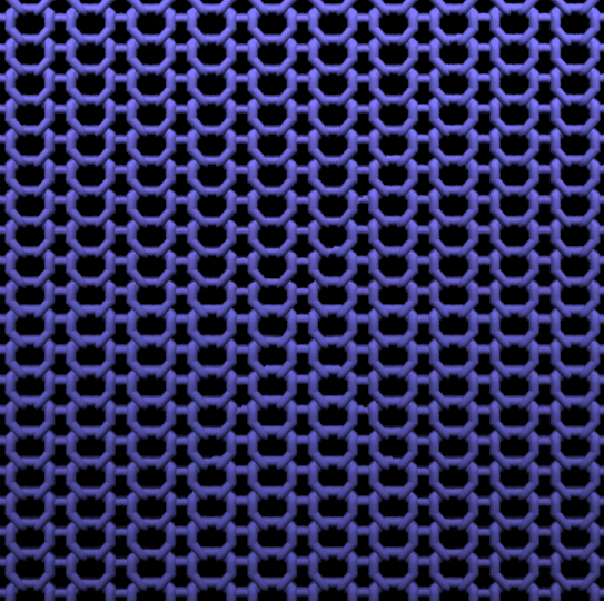
View lit from bottom:

View lit from left:

View lit from right:
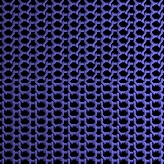
And finally a veiw of the afgan:
Challenges
This project was a large engineering challenge for me. There were many interum stages which each required a reasonable solution before I could view even the simplest image. I think alot of projects explore specific things like subsurface scattering or volumetric photon mapping. In my case I found virtual gonioreflectometry to be very interesting and thought cloth was a great thing to study since its a pretty complicated thing with many layers.
References
Lafortune, E.P.F., Foo, S.-C., Torrance, K.E. & Greenberg, D. Non-linear approximation of reflectance functions. Proceedings of SIGGRAPH (1997) pp. 117-126. http://citeseer.ist.psu.edu/lafortune97nonlinear.html
K. Dana, B. van Ginneken, S. Nayar, and J. Koenderink, "Reflectance and Texture of Real-World Surfaces," IEEE Conf. on CVPR, p. 151, 1997. http://citeseer.ist.psu.edu/dana97reflectance.html
Neeharika Adabala, Nadia Magnenat-Thalmann, Guangzheng Fei, "Visualization of woven cloth", 14th Eurographics workshop : http://portal.acm.org/citation.cfm?id=882430&jmp=cit&coll=portal&dl=ACM&CFID=15151515&CFTOKEN=6184618
Modeling and visualization of knitwear Groller, E.; Rau, R.T.; Strasser, W. Visualization and Computer Graphics, IEEE Transactions on Volume 1, Issue 4, Dec 1995 Page(s):302 - 310
HAUTH M., ETZMUSS O., EBERHARDT B., KLEIN R., SARLETTE R., SATTLER M., DAUBER K., KAUTZ J.: Cloth Animation and Rendering. In Eurographics 2002 Tutorials (2002). 73, 79
M. Cohen and D. Greenberg. The hemi-cube, a radiosity solution for complex environments. In Computer Graphics (SIGGRAPH '85 Proceedings), pages 31--40, 1985.
Katja Daubert, Jan Kautz, Hans-Peter Seidel, Wolfgang Heidrich, Jean-Michel Dischle,:"Efficient Light Transport Using Precomputed Visibility" IEEE Computer Graphics and Applications archive Volume 23 , Issue 3 (May 2003) table of contents
Project Proposal
I am interested in rendering fabrics in a pleasing way by taking into account their knit microstructure (combinging threads into cloth) and the composition of the threads (material and spinning structure).
I have attached 4 pictures of shirts I own that are made of different or have different weaves to the fabric. Based on the weave, there is some degree of self-shadowing and also transparency. My rough goal is to ray trace a representative small piece of the cloth in high detail and then bake the calculated BRDF, shadowing, and transparency into textures which can then be used to render larger patches of cloth.
The physical properties of moving cloth or cloth after it has fallen are not the focus of what I want to pursue.
So far I have two papers which look helpful and I am in the process of reading them:
A microsoft paper looking at cloth from many different perspectives: http://research.microsoft.com/~yqxu/papers/tvcg.pdf
A short paper looking at the individual fibers in a cloth: http://cgg-journal.com/2000-2/03/IMPLICIT.htm
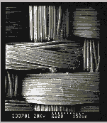
Some pics from second that illustrate microstructure:

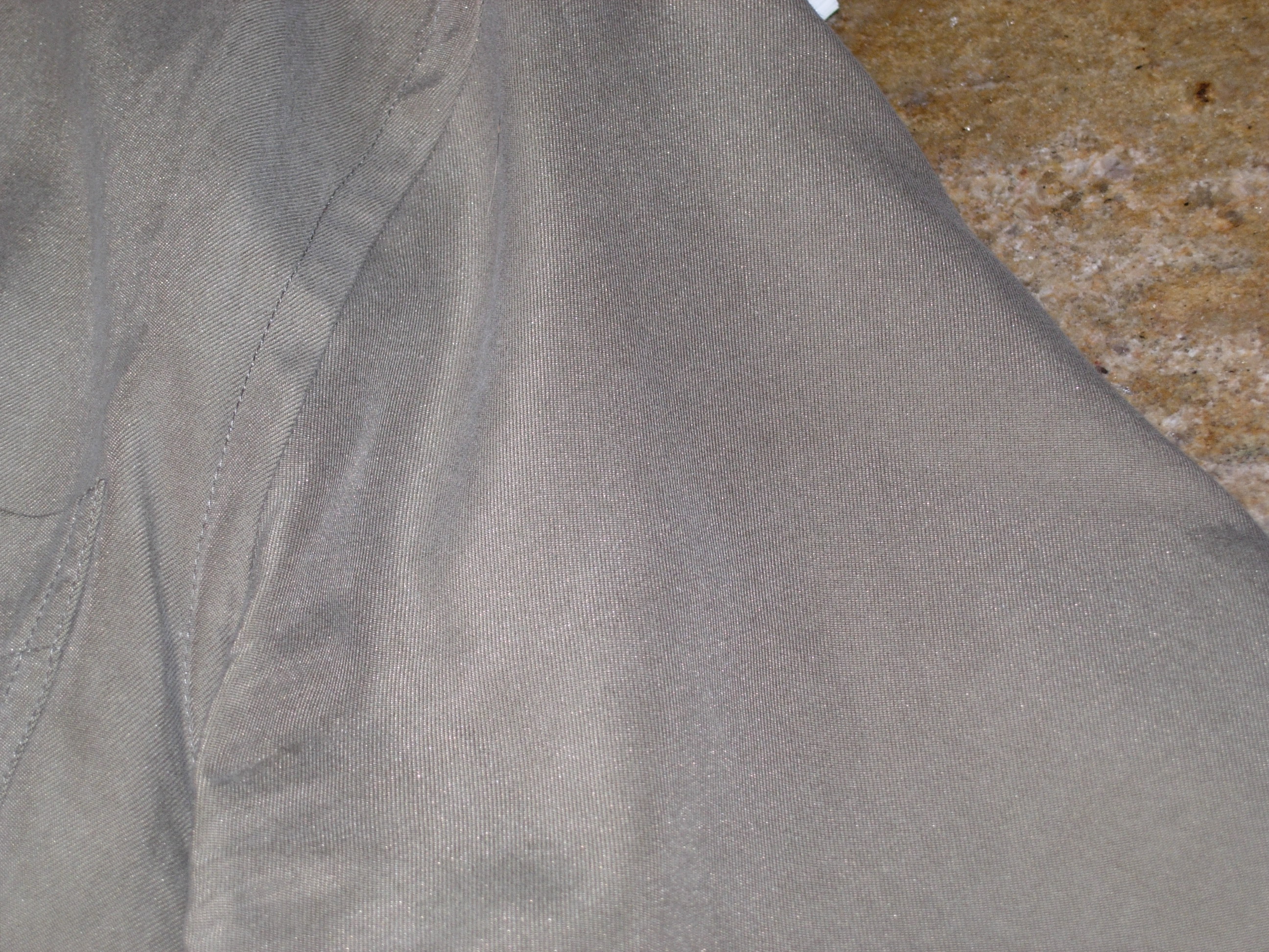
Some pics of my shirt fabric, VERY LARGE:


Upload new attachment "cotton_tshirt.jpg"
