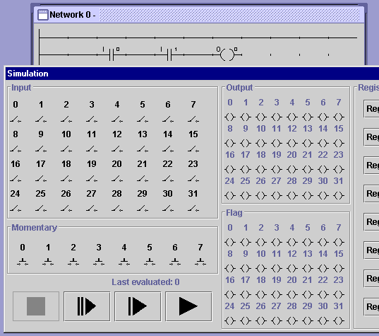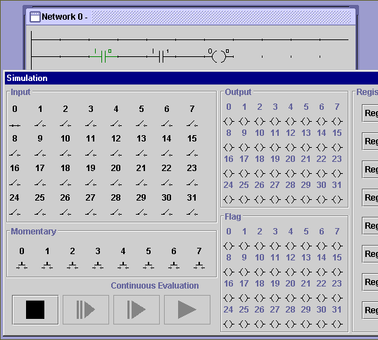

There are a lot of options in this window, but the controls are fairly simple. You can run, stop, or step through the simulation using the VCR-style buttons on the bottom left. You can control the values of the input lines by clicking on the switches on the top left. And, you can observe the values of output lines by looking at the "lamps" in the middle column. The right hand side of the simulation window allows you to inspect and modify 16 bit registers, but for now we don't need to worry about using those. Go ahead and press the play button to start the simulation, and then click on the toggle contolling input 0 (in the upper left corner). You should see something like this:

The first switch in the diagram is highlighted because it is receiving power (since input 0 is turned on in the simulation window). Powered components in a network are highlighted during simulation to show the flow of power through the network - this will make it easier to find mistakes in the logic when working with more complicated circuits. Now go ahead and click the toggle to turn on input 1. You should see something like this:

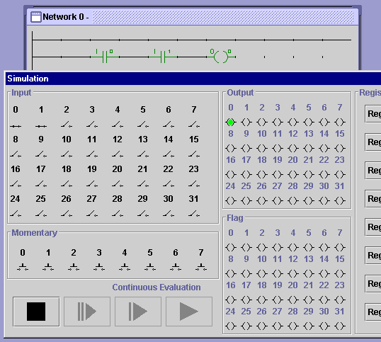
With both inputs turned on, all of the components have been highlighted in the network, and the lamp corresponding to output 0 has lit up in the simulation window. So when both inputs are on, the output turns on as well. You can see that this circuit acts like an AND gate, turning on output 0 only if input 0 and input 1 are both turned on.
Now that you have seen how the input and output lines assigned to components in a network correspond to switches and lamps in the simulation window, you're ready to begin designing and testing simple circuits. You can stop the simulation by clicking the stop button in the lower left of the simulation window, and then exit simulation mode by closing the window (by clicking the window-close button in the upper right corner). This will return the simulator to circuit design mode.
Try making an OR gate next; remember that you can place vertical shorts between two adjacent rungs in a network by right-clicking in the gaps between their tick marks.
Back to: CONTENTS