 Pause simulation
 Step one network *
 Step all networks *
 Continuous evaluation
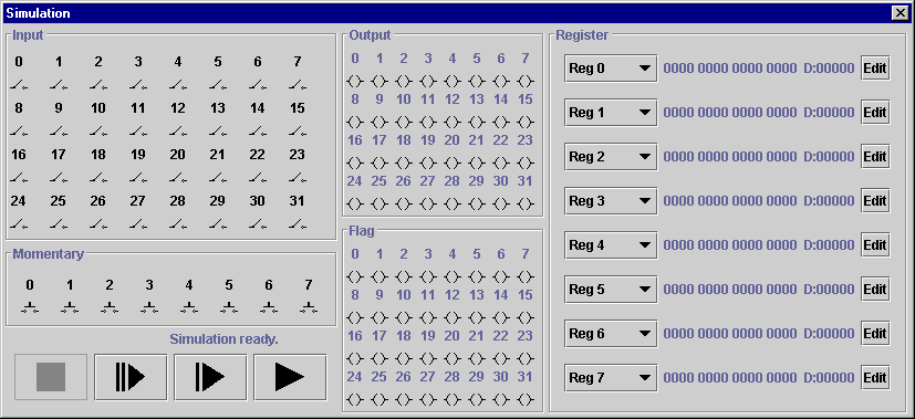
The VCR-style controls at the lower left of the simulation window control the evaluation of the ladder logic circuitry. From left-to-right, the buttons are:
 Pause simulation
 Step one network *
 Step all networks *
 Continuous evaluation
(Note: On some computers it may be necessary to manually
edit several simulation parameters in sim.properties to acheive
adequate performance in continuous evaluation mode. Consult the
File Format Documentation for sim.properties in the Technical
Information section of this documentation for more details.)
Immediately above the VCR controls is a status bar, which reports the current evaluation in progress. The status bar identifies the previously evaluated network during step-by-step evaluation, so that you always know exactly which networks have been evaluated at any given time.
The regular and momentary input toggle controls allow you to control the state of the various input lines. Note that pressing a momentary switch will have no effect unless the simulation is in continuous evaluation mode. Also, since the inputs are only polled prior to the each fresh evaluation cycle (starting with network 0), if a momentary switch is pressed for a very brief period it may not be polled while it is pressed.
The lamps in the middle column of the window show the current state of each of the output or flag lines in the simulation. An illuminated (green) lamp indicates that the associated line is logically high.
In the right hand column of the simulation window are the controls for inspecting and modifying registers. SimPLC maintains 1024 registers for use in your ladder-logic circuits, only eight of which can be viewed in the simulation window at one time. The combo box adjacent to each register entry allows you to choose which register to view in that slot.
Each register is displayed both as a 16-bit binary string, and as the corresponding decimal value. Clicking the "Edit" button next to a register will pop up a window allowing you to enter a new (decimal) value.
Back to: CONTENTS