
Improving the Efficiency of BRDF Representation
Szymon Rusinkiewicz
CS348c, Winter 1997
A look at current strategies for BRDF representation reveals that most general-purpose methods are too inefficient, particularly in storage cost, to be practical. Representations based on spherical harmonics, splines, Zernike polynomials, or spherical wavelets typically require tens of thousands of coefficients to represent even moderately complex BRDFs. We propose here a simple idea that, it is hoped, can be used in conjunction with any of these methods to produce substantial savings in the amount of data that must be stored to represent a BRDF accurately.
One problem with current BRDF representation techniques is that they are, essentially, schemes for representing arbitrary four-dimensional functions. They make no use of the symmetries and invariances commonly found in BRDFs. For this reason, they have trouble dealing with features such as specular peaks, and they provide no savings in storage for highly regular (for example, isotropic) BRDFs.
We propose, therefore, that there exist certain transforms that may be performed on raw BRDFs to put them into forms that the conventional BRDF representation techniques can compress more easily. These transforms, since they "know" that they are operating on BRDFs, can take advantage of the symmetries, near-symmetries, and invariances that hold for many commonly-encountered BRDFs.

One simple transform is taking the logarithm of the BRDFs. This transform uses the property that BRDFs often contain specular peaks that are several orders of magnitude higher than nearby areas. Therefore, taking the logarithm of the BRDF reduces the variance of the function that these methods must represent. In addition, if the logarithm of the BRDF can be represented with some specified minimum absolute accuracy, this will translate into a minimum relative accuracy for the BRDF itself. Because more absolute inaccuracy is allowed in the areas where the BRDF is large, fewer terms may be required to represent BRDFs with large variations. In practice, because the BRDF may fall to zero at certain points, it is necessary to use a function of the form log(a*x+1) instead of simply log(x).
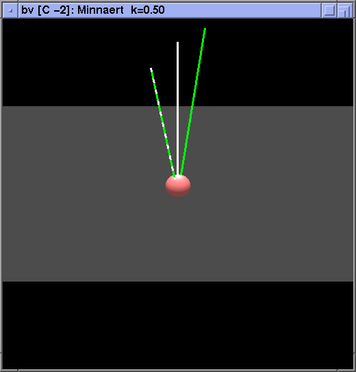
A second simple transform, often suggested in the literature, is to multiply the BRDF by cos(theta_in)*cos(theta_out) before storing it. This reccomendation is a consequence of the observation that many real BRDFs increase rapidly towards grazing angles. Strictly speaking, it is only necessary to multiply by one of the two cosines (typically theta_in), but multiplying by both preserves reciprocity. In any case, the benefit of this transformation is that the representation no longer has to deal with divergence at grazing angles, which it would otherwise have to represent for many real-world BRDFs.
We now turn to the main focus of the project, namely the change of basis transform. Changing the basis of BRDF data is particularly effective, because a large number of BRDFs contain extreme variation when looked at in the "standard" (theta_in, phi_in, theta_out, phi_out) basis. For example, consider the BRDF of a highly specular surface. In the standard basis, this BRDF will have sharp transitions throughout the four-dimensional space. It is not the presence of these sharp variations that is troubling, but rather the fact that they are not localized, particularly since we know rather accurately where they should occur. Another example of the inefficacy of the standard basis is that isotropic BRDFs can vary just as much in the standard basis as anisotropic ones - the simpler isotropic BRDFs in general produce no savings over the more complex anisotropic ones.
Therefore, we seek a basis in which the variation of typical BRDFs is as localized as possible. For example, there should be an axis along which there is no change for isotropic BRDFs. The peaks associated with specular highlights should be somehow localized in this new space. In addition, the reciprocity condition should correspond to some simple symmetry in the transformed space, both so that it can be enforced for measured data, and so that it can be used to reduce the storage requirements by one half.
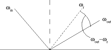
The most obvious basis that meets the above properties is the one in which the axes are the incoming direction (represented in polar coordinates), and the outgoing direction in the frame of refrence of the "reflected ray". That is, instead of considering the outgoing direction in the standard basis, we look at it in a (polar) coordinate system centered on the direction that is the ideal specular reflection of the incoming direction. It is easy to see that highly specular surfaces will have highly correlated peaks in this basis, and furthermore that there will be an axis along which isotropic BRDFs will remain constant.
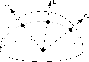
It turns out that the above basis works well for specular, isotropic surfaces, but not so well for many anisotropic ones. Therefore, we propose a new basis, consisting of the halfangle, and the position of the incoming ray in the frame of reference of this halfangle. Since the halfangle is defined as the vector halfway between the incoming and outgoing rays, it is clear that this basis is highly symmetric in terms of the angles of incidence and reflection, and therefore that the reciprocity principle corresponds to a simple symmetry in this basis. Furthermore, it is obvious that isotropic BRDFs in this basis will not vary with the "phi" of the halfangle. It is less obvious that specular reflection peaks should be compact in this basis, but it turns out that they are, both for isotropic surfaces and for many kinds of anisotropic specularity.
To test out the efficacy of these transforms, a program was written to display a large number of BRDFs in all of these bases. The program allows one to look at any number of bases and BRDFs simultaneously, for any angles of incidence and reflection. The displays are updated together as the angles are changed, so that one may compare different bases and different BRDFs side by side.
Some features of this browser are summarized here:
Note: please see http://www-graphics.stanford.edu/~smr/brdf/bv for the current version of bv. --- SMR 9/10/97
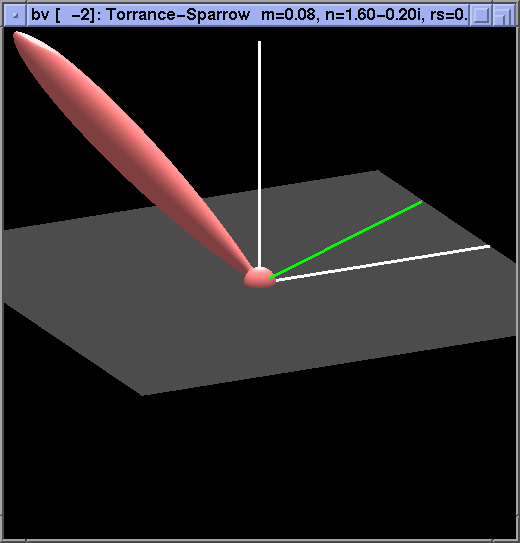
Here are a few examples of how some BRDFs look with the transforms given above. First, a demonstration of the effectiveness of the logarithm. This is a Torrance-Sparrow BRDF without logarithm
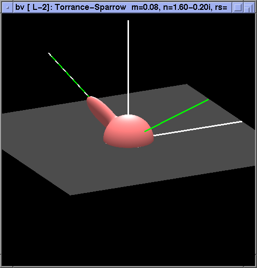
and with log.
Next, the Minnaert BRDF unmodified
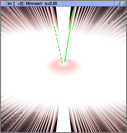
and multiplied by cos(theta_in)*cos(theta_out).
Next, we look at the "reflected angle" basis. We see that the specular peaks of isotropic BRDFs are well-localized, as expected.
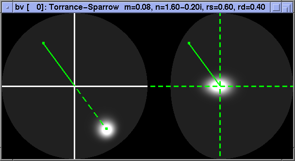
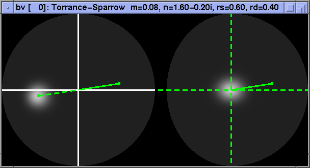
Anisotropic BRDFs, however, do not fare so well.
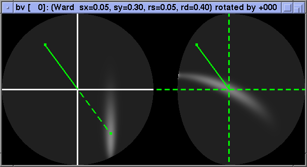
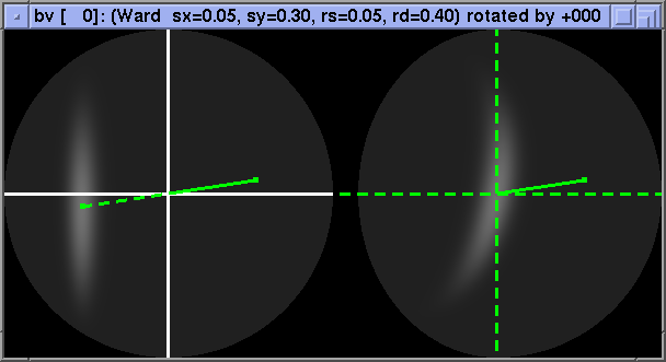
In the halfangle basis, isotropic BRDFs also show good localization:
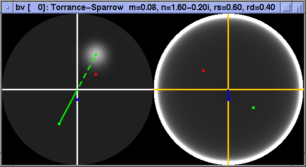
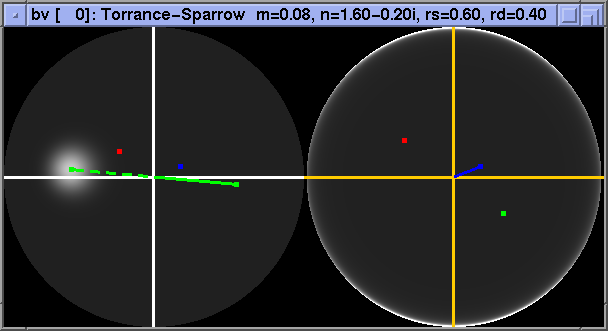
Anisotropy shows up as a gentle variation in intensity with phi_h:
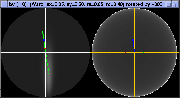
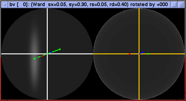
Retroreflective BRDFs show especially slow variation in this basis:
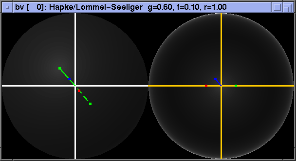
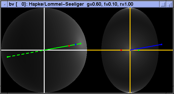
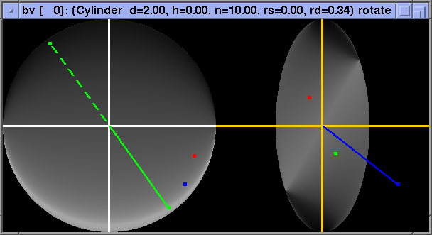
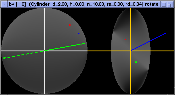
Finally, a (partial) failure case - the diffuse parallel-cylinder BRDF shows rotation of the whole "pattern" as phi_h changes. Note that this case fares no better in the "reflected angle" basis and, somewhat ironically, is best localized in the "standard" basis:
Transforming BRDFs into the "halfangle" basis should greatly increase the
efficacy of the standard representation/compression algorithms. Further
research should be done on quantifying the savings achieved by this change of
basis, and on selecting the best representations with which to integrate this
idea.
The BRDFs used for this project have all been synthetic - it proved too difficult to deal with the sparsely, irregularly sampled data of the currently available measured BRDFs. Therefore, here are some notes on the analytic BRDF models that have been implemented:
The infinite sum is evaluated directly for g < 15 (40 terms are used); otherwise, an analytic approximation is used, based on rewriting the sum (using the Sterling formula to approximate the factorial) as Summ=1inf exp(f(m)). The maximum of f(m) is found, and f is rewritten as a truncated Taylor series around the maximum. The resulting sum is then approximated by an integral of the resulting Gaussian.
Please see the Bibliography in my paper. Additional sources for analytic BRDFs are:
| [Glassner] | Glassner, A. Principles of Digital Image Synthesis, Morgan Kaufmann, San Francisco, 1995. |
| [Poulin 90] | Poulin, P. and Fournier, A. "A Model for Anisotropic Reflection", Siggraph 1990. |