CS 248 - Introduction to Computer Graphics
Autumn Quarter, 2005
Marc Levoy
Lecture notes for Thursday, November 3 (finished on Nov. 8)
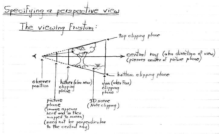
If you want to play with the program I used in class to demonstrate changing the field of view (zooming) versus changing the distance to the scene (dollying), then log on to a firebird or raptor and type:
/usr/class/cs248/support/bin/i386-linux/frustum.linux /usr/class/cs248/data/Inventor/spheres.iv


Notes:
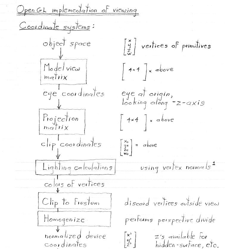
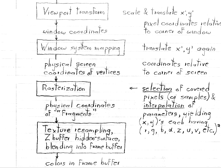
0. The pipeline above shows the progress of point, line, or polygon vertex coordinates through the OpenGL pipeline. It does not show the progress of vertex normals, texture coordinates, or colors.
1. The path for vertex normals is as follows. In Gouraud shading (the standard method), normals are transformed by the inverse transpose of the upper-left 3 x 3 submatrix of the Modelview matrix (as we learned earlier), they bypass the Projection matrix, and they are then used in a lighting calculation, to produce a color for each polygon vertex. We will learn about this lighting calculation later in the course. These colors are then interpolated across the polygon during rasterization. In Phong shading (an alternative method well-suited for rendering shiny surfaces), lighting does not occur where the pipeline above indicates. Instead, vertex normals are transformed as just described, then linearly interpolated across polygons during rasterization, to create a normal per pixel (a.k.a. per fragment). These normals are then used immediately in a lighting calculation, to produce a color for each fragment.
2. The path for texture coordinates is as follows. Each texture-mapped polygon carries a pointer to a particular texture, and each vertex of the polygon carries a (u,v) coordinate pair, which points to someplace in the texture. These coordinates are carried along without modification through the pipeline until rasterization. At that stage, they are interpolated across polygons using rational linear interpolation, as described earlier in the course. This produces per-fragment texture coordinates, which are then used to resample the texture, producing per-fragment colors. These colors are combined with the colors from the lighting calculation (using blending methods we haven't talked about yet) to produce final colors, which are eventually blended into the frame buffer using digital compositing (which we have talked about).
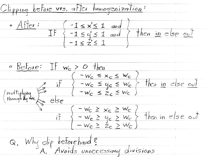
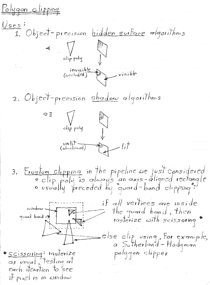
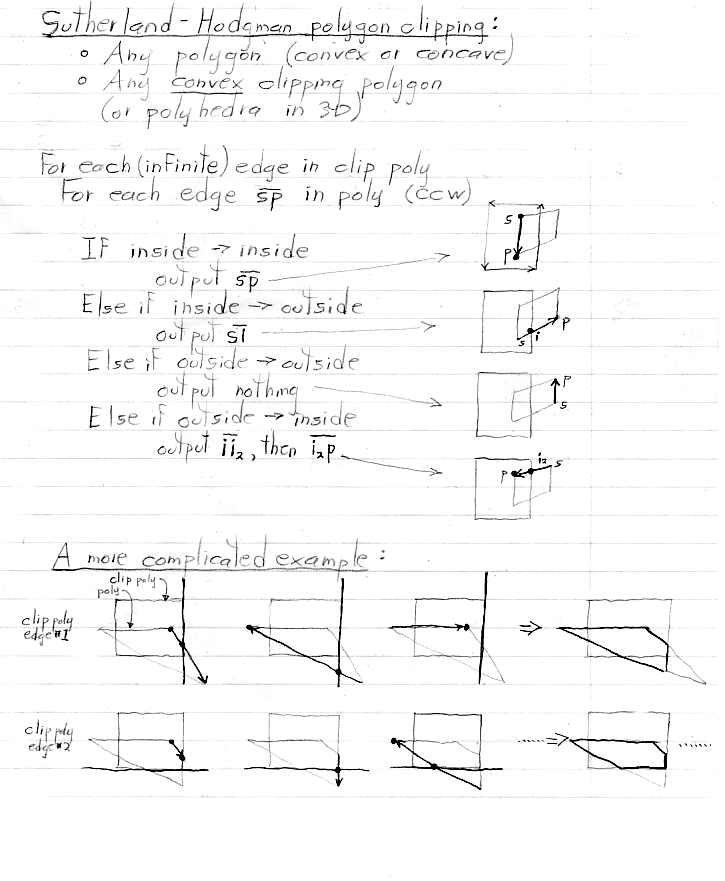
One further complication. When a polygon is clipped to the viewing frustum (a process we'll learn about shortly), vertices that are outside the frustum are discarded, typically to be replaced by new vertices that lie on the frustum boundaries. When this happens, the new vertices must be given normals, texture coordinates, and colors. This is done by interpolating these values from the vertices lying on either side of the frustum boundaries. This interpolation occurs before homogenization, so simple linear interpolation is used.


