CS348b Final Project - Simulating Interference effects in LRT: Iridescence in biological structures
Steve Bennett and Arthur Amezcua
Overview
The purpose of our project was to explore lightwave-dependent rendering.
We rendered a species of butterfly of the genus Morpho which has
iridescent wing scales. The butterfly appears to be bright blue to a
viewer looking down the wing normal, but as the viewing angle increases to
ninety degrees, the wings first appear purple then red, then finally dark
brown or black.
Iridescence
Morpho butterfly wings are covered in scales with a structure conducive to
generating iridescent colors. Each scale has 12 "mullion" which has a
higher refractive index than air. The width of these mullions is on the
order of certain light wavelengths. These mullions act as multiple layers
of thin films, which have the property of inducing interference in
incident light waves. Our project uses some of the mathematical results
from Smits and Meyer and Anderson and Richards (1942) to simulate light
wave interference on multiple thin films.
To accurately simulate interference, incident light must be represented by
a spectral energy distribution. However, in lrt colors are represented as
red, green, blue triples. As a result, we modified the color
representation WITHIN our iridescence BRDF. Our spectrum ranged from
360nm to 830nm, with values for the distribution defined at 95 wavelengths
-- every 5nm. Given an intensity for particular wavelength of incident
light, our code first calculates an intensity for outgoing light of that
same wavelength. Therefore, for each point to be shaded, we generate a
spectral distribution of the reflecting light. Then, using color matching
curves, we find the three intensities of X,Y, and Z colors that produce
the same color as the reflected spectral energy distribution. For the X
color, this calculation is:
X = k * integral(spectral_distr * color_x * d_lambda)
where color_x is the value of the X color-matching curve and k is:
1/(integral(spectral_distr_W * color_y * d_lambda)
where spectral_dist_W is the spectral energy distribution of the brightest
white.
After converting the spectral energy distribution of the reflected light
into X,Y, and Z coordinates, we converted the (X,Y,Z) representation into
an (R,G,B) representation. To do this we generated a 3x3 conversion
matrix. We followed a procedure outlined in Meyer and Greenberg: Using
the chromaticity coordinates of the white spot and phosphors of our
monitor, and the luminance of our monitor's white point (we chose a
relative value of 1), we derived a matrix that converts from (R,G,B) to
(X,Y,Z). We did this and then derived the inverse of this matrix to
obtain a matrix that converts from (X,Y,Z) to (R,G,B).
We created a surface type that has a shader (butterflyWingSurface) that
not only simulates multiple-thin-film interference, but it also adds a
slight glossy specular reflection and a perfect mirror reflection. Morpho
butterfly wings have a slight metallic appearance. The highlight color we
used was the color calculated by the iridescence code. One place we could
improve our shading work would be to change the surface glossy specular
color to the color of the lightsource. In pictures of these butterflies,
the wing surfaces have a sheen that appears to be a combination of the
iridescent color and the color of the light source. Finally, we bump
mapped the wing veins -- the final color due to iridescence and a metallic
reflection was multiplied by (1.,1.,1.) where there was no vein, and by
(.35,.35,.35) where there was a vein.
Modeling
Scene Creation and Modeling
The entire scene was modeled using 3d Studio Max 4.0 on a PIII-1GHz,
Win2K. Specifcally, the butterfly wings and leaves were created using
deformable mesh subdivison surfaces allowing easy contouring. We used our
proposal photograph as a viewport backgound and deformed the wing and leaf
meshes until they were the same shape and contour as their corresponding
counterparts in the photo. The butterfly body was created using a 2D
spline path followed by a "lathe" operation which rotates the spline path
in 3D creating a solid with cylindrical symmetry. The eyes of the
butterfly were modeled just with simple spheres since the level-of-detail
at the viewing distance was not high.
Once the geometry was created in 3D Studio Max, we exported the geometry
as a RIB using an evaluation version of MaxMan, a 3d Studio plugin from
AnimalLogic. (thanks to Jeff Mancuso for that hookup...)
Textures and Surfaces
All geometry in the scene except the butterfly eyes were texture-mapped in
some way. Specifically, the borders of the butterfly wings, the butterfly
body, and the leaves were all textured-mapped as decals. The leaf textures
were obtained on the web at various botany resources, and the butterfly
body texture image was obtained at 3dcafe.com. The texture images for the
butterfly wing borders were hand drawn in black and white in Photoshop
6.0, followed by the application of monochromatic noise and a gaussian
blur to create a less "clean," more realistic looking wing border.
The actual butterfly wing surfaces themselves used bump mapping - we
carefully drew the vein structure in Photoshop in grayscale, and used
the color values in the resulting images to modulate the iridescence
effect on the surface, resulting in decent veins that are integrated into
the iriscence effect rather than just glued onto the surface as a decal.
Challenges in scene geometry and texturing
We ran into many significant obstacles in the scene production phase of
the project - getting a RIB out of 3dStudioMax and MaxMan that LRT could
handle was challenging. We needed make sure that our meshes were output as
"PointsPolygons" since LRT does not implement "PointsGeneralPolygons"
apparently. It was also tricky to get the texture coordinates and
LightSource properly output into the RIB as well. We ended up writing a
few perl scripts that took our 3dStudio RIBs and converted them into a
form LRT could read and render. (These scripts are included in our
gzipped and tarred project file on the web page)
Animation
To really appreciate the iridescence effect in our rendering, an animation
is necessary, since the change in color over varying viewing angle is lost
in a static overhead image of the morpho butterfly. The amimation frames
were made in 3dStudio Max, and was relatively straighforward. We used
keyframes and tweening in 3Dstudio max to set start and stop
positions/rotations for the camera, and 3DStudio Max exported 30 RIBs
representing the frames in between. After converting each of these
animation RIBs to a form LRT could handle using the aforementioned Perl
script, we used another Perl script to batch-render these one at a time on
a few different machines. The resulting 30 still images were then encoded
in MPEG-1 and MPEG-2 formats for playback at the Friday demo using a
windows application VideoWare III.
Images
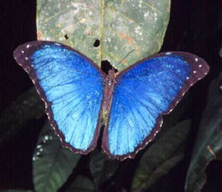
Original Photograph
Rendered Image -- viewing angle zero degrees
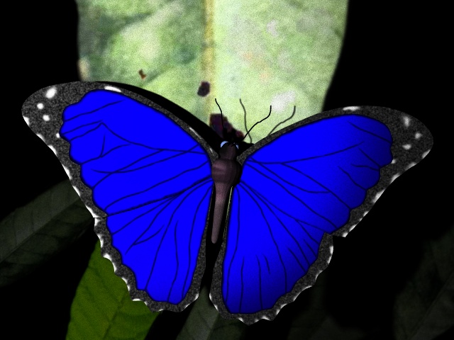
(get tiff here)
Rendered Image -- viewing angle approximately 45 degrees
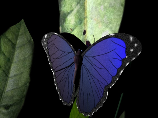
(get tiff here)
Rendered Image -- grazing viewing angle
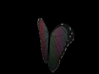
This image shows the nice spectrum of colors that appear at grazing
angles when the light is behind the surface position being viewed.
Here is a movie in which the camera pans
over the butterfly from a grazing viewing angle to an overhead viewing
angle to another grazing viewing angle. The light and scene remain
stationary, only the camera moves. The color of any position on the
surface of the butterfly's wings depends on the viewing angle.
Here is the source code for rendering
these images.
Last modified: Sun Jun 10 20:19:48 PDT 2001