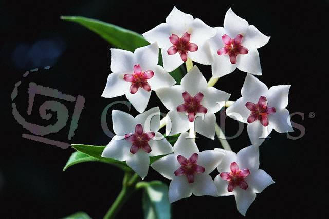
For my final project, I generated an image of a flower bunch based on the following picture (disregarding the watermark label).
I chose this picture, because I like the simplicity of its beauty. The white petals form a clean star-shape, accented delicately by the inner red petals. The thin yellow pollen at the very center of each flower add a nice final touch.. The stem and petals in particular have a very soft, natural look to them. In this project, I attempted to duplicate the look and feel of this picture. I first modeled the flower in Maya and exported the scene as a RIB file. I then rendered it using lrt, which I had modified to include depth of field and subsurface light scattering.
I used Alias|Wavefront's Maya to model the petals and leaves using NURBS surfaces. I placed CV points along one half of their silhouettes and then revolved them to get the surface. I flattened these surfaces to an appropriate thickness and then pulled in one half of the CV points to get the right concave shape of the petals and leaves. For the flower part, I rotated each petal a bit so that they would not be in a perfect (unnatural) star formation. Then I rotated and translated specific CV points for each petal and leaf so that they would not all be identical (which would, again, be very unrealistic).
I used NURBS cylinders to model the stems and pollen. I rotated and translated certain CV's to give them the right curvature and look.
I used a simple NURBS plane to model the back wall.
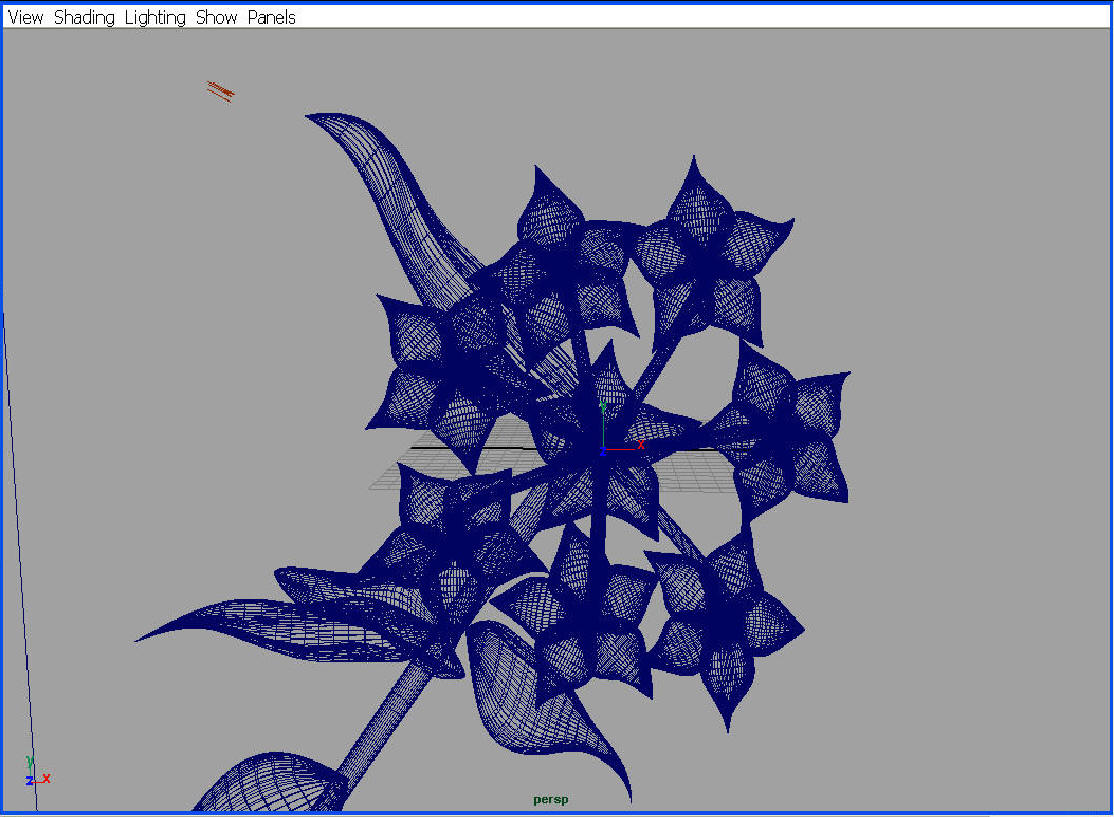
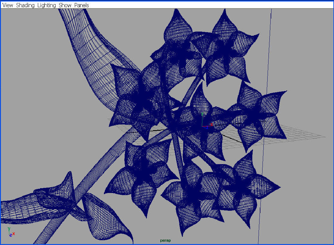
Here are a couple screenshots of the wireframe model of the scene I created:
I used the Maya plugin MayaMan (http://www.animallogic.com/research/mayaman/) to translate my flower model to an lrt-compatible RIB file. MayaMan did a fairly good job of exporting an RIB file readable by lrt. However, I still had to go into the RIB file and hand tweak it to make it completely compatible with lrt.
A pinpoint camera shoots out one ray from the eye to the object, since the eye is located at one specific location. However, for a camera with a lens of finite size, the origin is different depending on its location on the lens. Thus, the lens surface must be sampled randomly for this origin point. The ray is then sent out to intersect at the same point on the focal plane that was hit in the pinpoint camera case. This allows for things located at the focal plane to be in focus, while things at different depths than the focal plane be out of focus.
Motion blur is simulated by implementing a finite exposure time and having the camera move. The aperture time can then be randomly sampled, resulting in random camera locations along its motion path.
To give the petals their soft, realistic look, I will implement sub-surface light scattering. Incident light will be partially reflected off the surface and partially refracted through the surface. This refracted light will be repeatedly reflected and refracted off the inner layers of the surface. Some of this light will be absorbed, some will be transmitted through the surface, and some will re-emit through the layer it initially penetrated.
I will be basing my implementation on that presented in the paper: "Reflection from Layered Surfaces due to Subsurface Scattering" by Hanrahan and Krueger, Computer Graphics Proceedings, Annual Conference Series (1993), 165-174. As this paper shows, plant cells create a layered surface that works well with this light scattering model.
The reflected radiance is the sum of the radiance due to surface scattering and that due to subsurface scattering. The transmitted radiance is the sum of the radiance transmitted due to absorption and that due to subsurface scattering. Using these functions, the bi-directional reflection-distribution function (BRDF) and bi-directional transmission-distribution function (BTDF) can be calculated. The influence of the surface and subsurface components of these functions depends on the Fresnel coefficients of the layer material. The Fresnel coefficients reflect how light acts when hitting such a material: how much light is reflected, how much is refracted, and at what the angle the light is refracted. For example, if the Fresnel reflection of the material is low, a relatively greater amount of light penetrates the surface and therefore subsurface scattering has greater weight.
Here is a link to my source code.
Here are some of my final renderings. Here's a link to the RIB files used to obtain these images.
A future step I could take would be to implement soft shadows using a distribution ray tracer modeling area light sources and penumbrae. I could use a BRDF to model the ray distribution emanating from each surface. Veach's paper on bidirectional ray tracing (Siggraph '90) would be a good reference for this approach.
Hanrahan and Krueger. "Reflection from Layered Surfaces due to Subsurface Scattering." Computer Graphics Proceedings, Annual Conference Series (1993), 165-174.