|
Shane Witnov -- Rahul Gupta
(Original
Proposal)
TARed Code
Thin-Film Interference
This was implemented by simulating the physics of a real interference pattern
on a surface with a single thin layer. The layer was chosen to be 700nm and
was then modulated by a noise function. When an eye ray intersected the
surface the distance it would travel to hit the inner surface was calculated.
This distance was added to the distance the light ray would take to hit the
same point. This distance value was compared to the distance that would be
required to have perfectly constructive interference for red, green and blue
light. Then the RGB values of the incoming light were scaled appropriately
and added to the final color of that pixel.
Miscellany TFI Comments
To calculate the background color of the shell, I took the input color for
the RIB file, modulated it with a noise function and then added a specular
highlight. To get the thin film interference working on more interesting
models, I also had to add UV coordinate mapping of nurbs to LRT.
Results
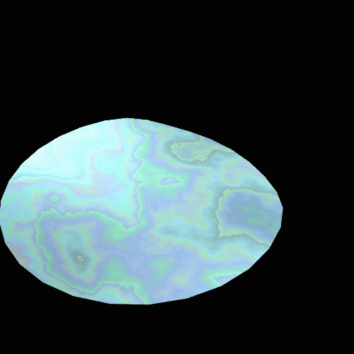
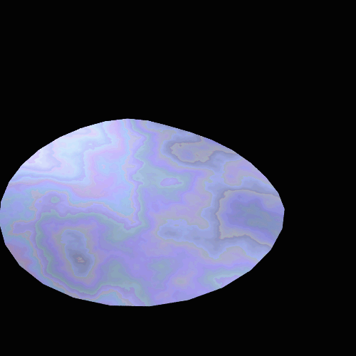
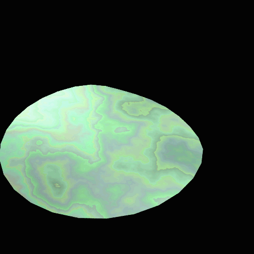
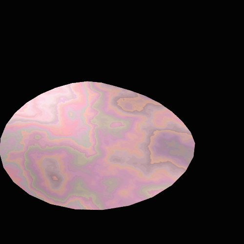
The final renders turned out pretty well. The interference patterns resembled
those on abalone shells and seemed to modulate approximate correctly when the
view point was changed. Here are
some examples of the abalone under different colors of light. In order they are blue/green, blue,
green, and red. (Note that the
light is not monochromatic, just more strongly in one part of the
spectrum). The video shows how
the interference changed as the camera moved.
Short
Video (Sorenson 3)
Fractal Terrain
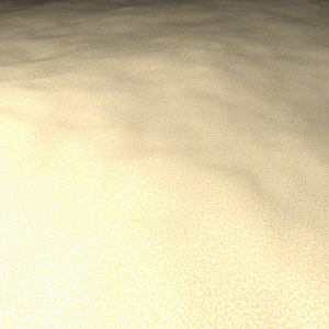
As a prelude to bump-mapping the surface of the abalone, we decided to
experiment briefly with random terrain generation and texturing in the
context of sand-like surfaces, since any abalone image we rendered would look
more realistic if placed upon a beach. To that end, we implemented a system
based on the "Diamond-Square" fractal algorithm described in:
http://www.javaworld.com/javaworld/jw-08-1998/jw-08-step_p.html
We constructed a new "Fractal" class that generated a randomized
grid of Z-coordinates, and then had the heightfield constructor copy this
grid, instead of initializing Z-coordinates from a data file. Just for fun,
the sand-like color patterns used to texture the heightfield were generated
through a Perlin noise function downloaded @
http://astronomy.swin.edu.au/~pbourke/texture/perlin/
The noise function was used as the basis for a random inteprolation between
two colors, the result of which was passed to the LambertianReflection()
function in Matte::GetBSDF().
Bump Mapping
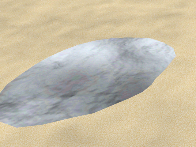
We decided to bump-map objects by indexing into a heightfield structure using
a given facet's UV-coordinate pair. As our test abalone surfaces were
2-dimensional planes, constructing a coordinate system around the original
surface normal was straightforward. The normal vector returned from the
heightfield was then passed through a facet's coordinate system, with the
resulting perturbed normal being used to shade the object. We also
experimented with bump-mapping the beach surface. By varying the perturbation
amount, we could enhance the bumpiness of the sandy surface without actually
recomputing geometry. It would be interesting to further experiment with
laying bump maps over heightfield geometry - by animating the U,V coordinates
used to index into the bump map, we might be able to "push"
shadow-like spots across the surface of the field, and thus simulate simpler
versions of caustics and other underwater effects.
Short Video (Sorenson 3)
The above video shows the basic effect of layering a
"heighfield as bump-map" over heightfield geometry. By decreasing
the perturbation amount over time, one can see the effects of the bump-map
fade over time.
Bump-mapped abalone fragments
Short Video (Sorenson 3)
|


