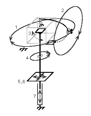
Schematic of large-roller gantry
sketched by Marc Levoy
July 12, 1996 version
(not drawn to scale)

Degrees of freedom
- 360-degree roller bearing large enough to enclose axis 2
- 360-degree axis with interchangeable arms for cameras
and opposing backdrops
- -90 to +90 degree
tilt table supporting interchangeable
platforms for samples and objects
- 360-degree axis supporting the tilt table
- 3-6 inches of X translation to adjust object center
- 3-6 inches of Y translation to adjust object center
(or more to include sweep)
- 6-12 inches of Z translation to adjust object center
Advantages over the July 11 design
-
By placing the roller bearing at the equator, the vertical post supporting the
camera axis (DOF 2 in the diagram) is removed. This should improve stiffness
and reduce cost.
-
For full-surround light fields, where the camera must orbit completely around
the object, there is a cone of prohibited angles from which objects can be lit
due to shadows cast by the gantry on the object. In the July 11 design, the
posts are assumed to be thick enough to shadow the object, so the cone of
prohibited lighting angles extends from the equator down to the bottom of the
posts. In the July 12 design, only the equator, where the roller bearings are,
is prohibited.
-
For BRDFs and BDTFs, since the light cannot be placed anywhere along the
equator, a fixed light is placed somewhere above the equator and the object
platform includes a tilt table. By eliminating the post and arm for the light,
cost is reduced.
Disadvantages relative to the July 11 design
-
The roller bearing must be much larger. Its radius is now determined by the
camera standoff distance (30 inches) rather than the radius of the working
volume (8 inches) as before. This might increase cost.
-
The camera arm must be curved to fit within the roller bearing, and the entire
camera and its wiring must also fit within this space. In the July 11 design,
the camera only needed to fit within the radius of the light source arm, which
is more flexible and could even be modified in the future.
-
For single-sided light fields, the cone of prohibited lighting angles in the
July 11 design does not wrap completely around the object, because its equator
is unobstructed. This is better than the July 12 design, in which the equator
is always completely obstructed.
-
For BRDFs and BTDFs, the use of a tilt table means that the object would have
to securely affixed to the object platform.
-
For light fields, lights could be placed above or below the
equator, but not at the equator, and care must be taken to avoid casting
shadows of the roller bearing assembly on the object.
levoy@cs.stanford.edu
Copyright © 1996 Marc Levoy
Last update:
Monday, 26-Apr-2004 18:24:59 PDT
