during a visit by Marc Levoy
to the laboratory of Rudolf Oldenbourg and Shinya Inoue,
Marine Biological Laboratory, Woods Hole, MA, May, 2006
|
|
during a visit by Marc Levoy
|
|
For an introduction to our project, see the project's
home page.
For a detailed description of how light field microscopy is done, see our
SIGGRAPH 2006 paper.
May 3, 2006
Specimen: Rudolf Oldenbourg
DIC microscope setup: Michael Shribak
Photography, processing, web page: Marc Levoy
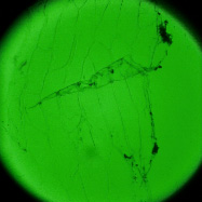
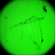
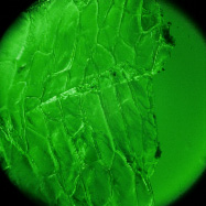
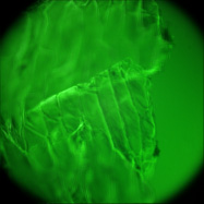
The goal of this experiment was to confirm that light field microscopy is compatible with DIC illumination. The microscope was a Zeiss Axiovert with a 20x/0.5NA (dry) objective. The microlens array was 24mm x 36mm, with square 125-micron x 125-micron f/20 microlenses, held in front of the Axiovert's side camera port using an optical bench mount. The camera was a Canon 5D full-frame digital SLR. The specimen was the thin silky skin separating two layers of an onion, immersed in oil to improve transparency. Transmitted illumination was used, from a fiber EXFO X Cite 120 PC fluorescent illumination source conducted through a multi-mode fiber with a 3mm liquid core. A diffuser was placed near the fiber tip to improve angular uniformity. Although this experiment was successful, light field microscopy is not compatible with Zernike phase illumination. If one tries to capture a light field using a phase objective, the phase ring will appear as an opaque circle in each microlens image,
Brightfield illumation
|
 (or AVI) Shown at full size, but movie is magnified 1.5x |
 (or AVI) Shown at full size, but movie is magnified 1.5x |
|
Rectified light field (187 x 187 x 20 x 20 samples) |
Synthetic panning sequence, 60 degrees of angular parallax (about 50 degrees shown here) |
Synthetic focal stack, 31 slices 5 micron apart in Z |
DIC illumation
|
 (or AVI) Shown at full size, but movie is magnified 1.5x |
 (or AVI) Shown at full size, but movie is magnified 1.5x |
May 8, 2006
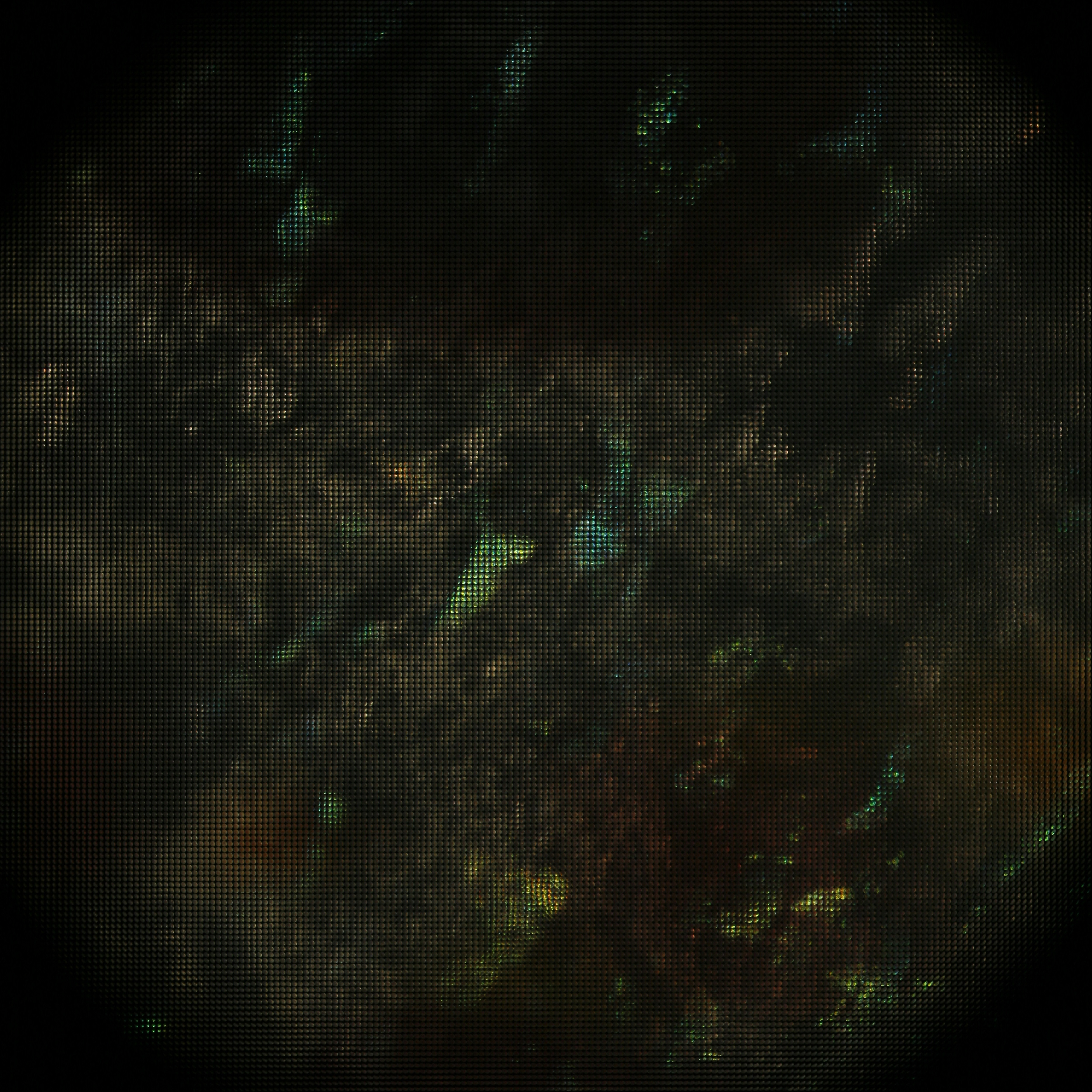
Since Bertrand lenses produce images of a microscope's aperture rather than its field, they essentially transpose the light field passing through the microscope. Since our microlens array records the entire light field (in sampled form), we should be able to visualize this transposition as a re-ordering of the pixels in the recorded image. The microscope, objective, microlens array, and specimen was as in the previous experiment. The particular view shown here is of an air bubble trapped in the slide. DIC illumination is used.
Field (i.e. specimen) plane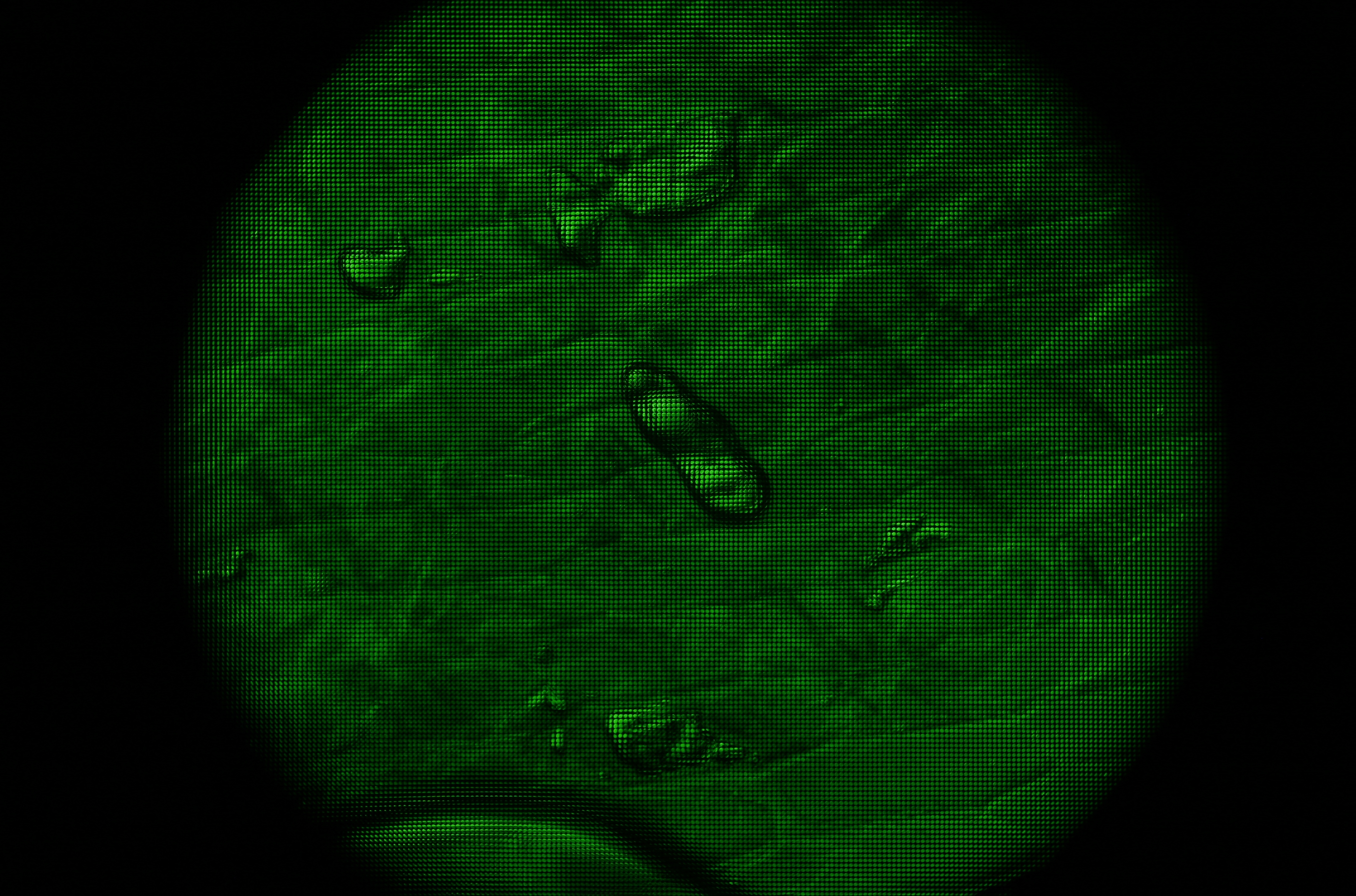
|
Aperture (i.e. objective back focal) plane
|
|
Each microlens image disk shows multiple directions of view for one point on the specimen (as usual) |
Each microlens image disk shows the entire specimen for one direction of view |
May 9, 2006
Specimen: Roger Hanlon
DIC microscope setup: Rudolf Oldenbourg
Photography, processing, web page: Marc Levoy
Light field microscopy can be used not only to study how the geometry of a specimen changes when viewed obliquely, but also how its appearance changes as a function of the angle between the illumination and the point of view. The microscope was a Zeiss Axiovert with a 20x/0.5NA (dry) objective. The microlens array was 24mm x 36mm, with square 125-micron x 125-micron f/20 microlenses. The specimen was a fixed sample of squid skin immersed in water. A Fiber-Lite MI-150 fiber optic source was used, conducted to a point 20cm from the specimen and declined below it (on the inverted scope) about 20 degrees.
|
 Shown at full size, but movie is magnified 1.5x |
 Shown at full size, but movie is magnified 1.5x |
|
Rectified light field (187 x 187 x 20 x 20 samples) |
Synthetic panning sequence, 60 degrees of angular parallax (about 50 degrees shown here) |
Synthetic focal stack, 26 slices 5 micron apart in Z |
May 16, 2006
Specimen: Lydia Mathger
Microscope setup: Michael Shribak
Photography, processing, web page: Marc Levoy
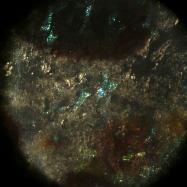
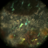
Extending the above idea, the goal of this experiment was to explore whether scatterometry can be performed using a light field microscope, assuming one also has control over the illumination direction. In particular, we try to measure the spatially varying bi-directional reflectance distribution function (BRDF), sometimes called the bi-directional surface scattering reflectance distribution function (BSSRDF), of a (more or less opaque) surface. The microscope was a Zeiss Axiovert with a 20x/0.5NA (dry) objective. The microlens array was 24mm x 36mm, with square 125-micron x 125-micron f/20 microlenses. The specimen was a live (recently dissected) sample of squid skin, partly dried to avoid dripping water on the microscope objective. A 3:1 macro lens was used on the Canon 5D camera. With these relay optics, each microlens image measures 45 (Bayer mosaic) pixels across. Using a 20x/0.5NA objective, there are about 12 resolvable spots across a microlens; the rest is empty magnification. Nevertheless, using this arrangement we can produce useful views of the angular dependence of scattering for a single squid skin iridiiphore.
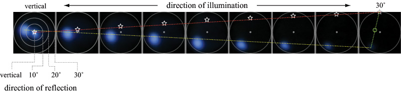
(a) Specular reflections. Using a mask placed at the condenser aperture plane, illumination from a mercury arc source subtending 10 degrees was moved by hand to 9 incident directions, ranging from vertical (the microscope's optical axis) to 30 degrees away from this axis (the maximum permitted by our 20x/0.5NA objective). For each illumination direction, a light field was captured, and a set of 6 microlens images having no iridescence were averaged together, producing the 9 images above. The yellow line is a linear fit to the path taken by the surface highlight as the light source was moved. The red line and white stars show the estimated direction to the light source. The direction of the light was known to be vertical (on the optical axis) in the left image and at the top of the aperture in the right image; however, its position along this path for each image is only approximate, since the mask was moved by hand. The green line and circle show the estimated surface normal, halfway between the light and highlight. The surface thus pointed slightly to the left. The second highlight in the leftmost image is due to internal reflections in the microscope.
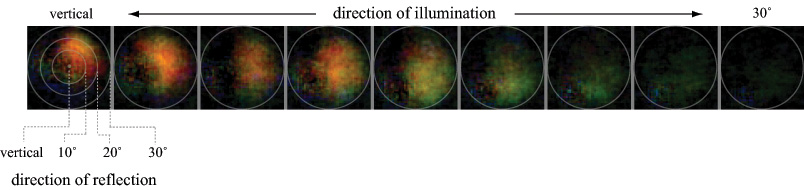
(b) Iridescence. For each light source position, a 3 x 3 set of microlens images was averaged (reducing noise and allowing for specimen motion). Specular reflections (shown in (a)) were then subtracted and the result scaled for display. At normal incidence, this iridiphore apparently iridesces red-orange and preferentially to the right relative to a plane passing from the illumination direction through the surface normal to the specular reflection direction. As the illumination declines toward the horizon, the iridescence changes to green and rotates around towards the specular highlight direction.
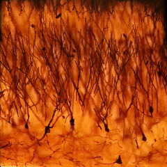
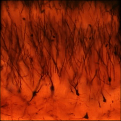
May 26, 2006
Specimen: Paul Rhodes and Katherine Lewin
Photography, processing, web page: Marc Levoy
The microscope was a Zeiss Axiovert with a 40x/0.85NA (dry) objective. The microlens array was 24mm x 36mm, with square 125-micron x 125-micron f/20 microlenses. The specimen was a 150-micron thick slice of Golgi-stained turtle cortex neurons (slide #A116.15) with cover slip. Illumination was brightfield. The slide was translated by hand through a 3x3 grid of positions with substantial overlap (see discussion below). The individual light fields were then rectified using a common warp and mosaiced together by hand in Photoshop with 80 pixels of feathering around each light field. The resulting mosaic light field was then cropped slightly to hide its uneven boundaries, yielding a 4800 x 4800 pixel image.
Since a microscope's stage is precisely perpendicular to its optical axis, rectification needs only to compensate for roll of the camera relative to the microlens array, and radial distortion in the optics (not done), shear due to inaccurate sensor placement (typically none). The rectification program used here (Andrew Adams's ImageStack) also scales and translates the light field image in X and Y until the microlens subimages are centered at known pixel positions. Since microscopes are orthographic, the mosaicing step consists simply in translating the individual light field images relative to one another until features of the specimen are aligned between images, then either cutting and abutting the images together or overlapping and blending them. No perspective projection is necessary, and there are no parallax errors in the resulting mosaic for objects close to the microscope objective, as would happen in an ordinary photographic mosaic.
Magnified 40x (0.85NA)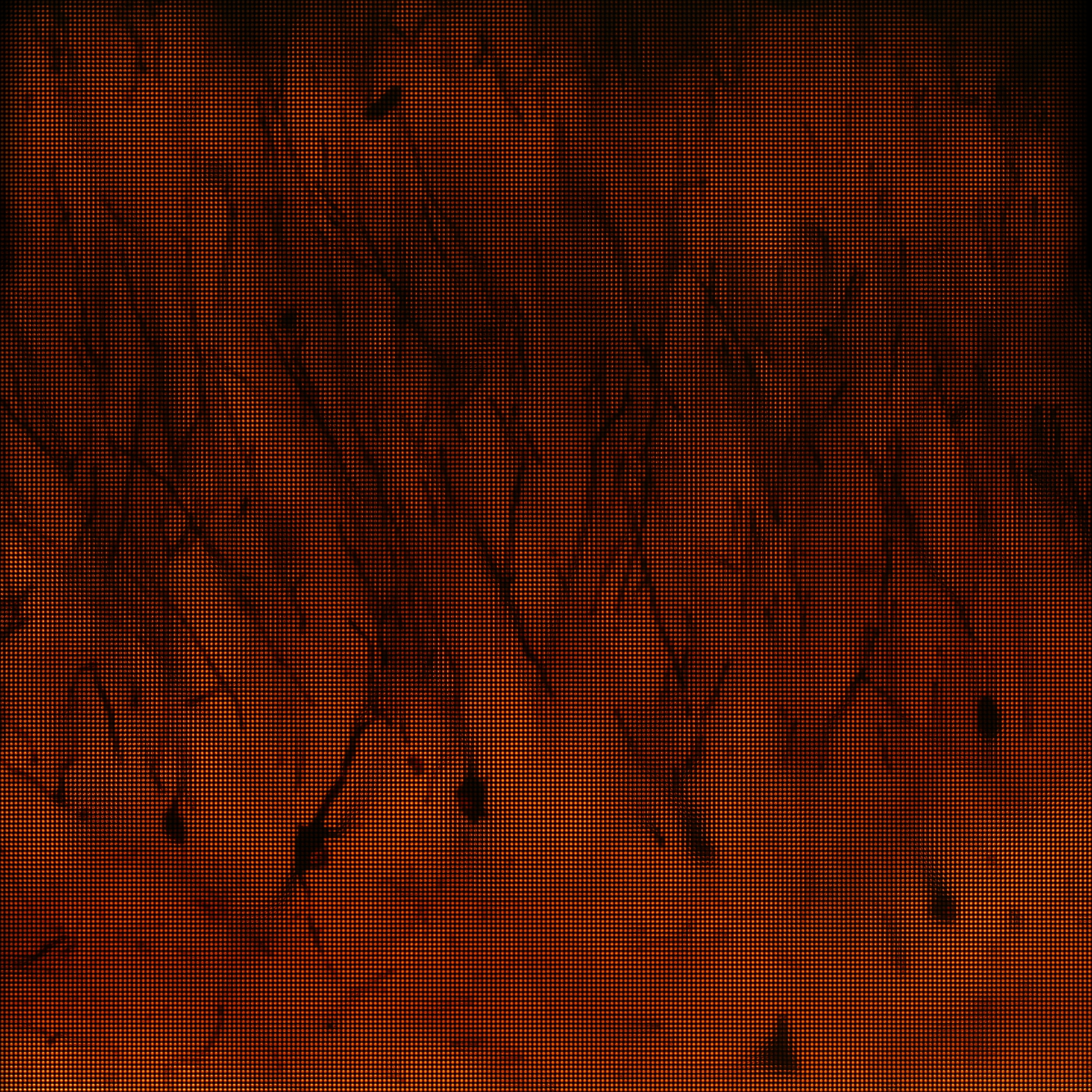
|
 (or AVI) shown at full size, but movie is magnified 1.5x |
 (or AVI) shown at full size, but movie is magnified 1.5x |
|
Mosaiced light field (240 x 240 x 20 x 20 samples) |
Synthetic panning sequence, 120 degrees of angular parallax (about 80 degrees shown here) |
Synthetic focal stack, 17 slices 1 micron apart in Z |
In general this worked well. In fact, it worked so well that if the individual light fields are mosaiced together without blending the seams are only visible (in at pan sequence) at the extreme edges of the aperture. Click here to see the unclipped light field with blending (against black) and without blending (against white).
However, there are two problems. First, images taken through circular apertures do not tile the plane unless captured with substantial overlap. Translating the stage through a rectilinear grid exacerbates this problem; a hexagonal translation pattern would have worked better. Therefore, the stage was translated only about 30 microlenses per grid position, which isn't much since each light field was itself 188 microlenses wide. This made the 3x3 mosaic only 240 x 240 microlenses - not a lot larger than a single light field. I was being more conservative than necessary.
Second, it is impossible to translate the stage (at least by hand) an integral number of microlenses per grid position. (Each microlens covers about 3 x 3 microns on the specimen). Thus, no 2D mosaicing program (such as Photoshop) can precisely align the individual light fields to each other; any such resampling might be off by half a microlens (i.e. one unit in s or t), hence half a pixel in the resulting synthetic images. I see no artifacts in the above pan and focal sequences due to this half-pixel error; however, it must be present. Solving this problem would require a 4D translation and resampling program, in which each output microlens image is computed by blending together a neighborhood of input microlens images with appropriate weights.
Finally, it is worth remembering that, while this protocol allows larger images to be created, it gives up the advantage of capturing the scene in a single snapshot. However, if the overlap between adjacent tiles can be minimized, it still allows a focal stack to be captured with less light damage than if the stack were acquired using a motorized Z-stage.
May 30, 2006
Specimen: Susan Barrett (Frontiers in Reproduction)
Microscope setup, photography: Rudolf Oldenbourg
Processing, web page: Marc Levoy
The goal of this experiment was to determine if the number of cells in a live embryo could be counted from a single photograph, hence minimizing observation time and phototoxicity. This ability has implications for in-vitro fertilization. The microscope was a Zeiss Axiovert with a 40x/0.85NA (dry) objective. The microlens array was 24mm x 36mm, with square 125-micron x 125-micron f/20 microlenses. The camera was a QImaging cooled CCD with 1600 x 1200 pixels. (The small size of this sensor chip accounts for the small number of pixels in the output images.) The specimen was a collection of mouse eggs and embryos in different stages of division (up to about 4 cells), sitting at the bottom of a drop of fluid medium, which sat in a cover-slip-thickness, glass-bottom dish. The drop was immobilized and prevented from evaporating by covering it with a layer of oil. The condenser was 1.4NA oil immersion (and was immersed into the oil), but stopped down to about 0.8 to avoid loss of contrast due to scattered light. The Illumination was DIC. Note that in a static image, it appears that the central embryo contains only three cells, suggesting a non-viable embryo. However, by rotating or digitally focusing through it, a fourth cell can be seen.
Magnified 40x (0.85NA)
|
 (or AVI) shown at full size, but movie is magnified 2.0x |
 (or AVI) shown at full size, but movie is magnified 2.0x |
|
Rectified light field (92 x 69 x 20 x 20 samples) |
Synthetic panning sequence, 120 degrees of angular parallax (about 60 degrees shown here) |
Synthetic focal stack, 33 slices 1 micron apart in Z |