Assignment 3 Camera Simulation
Name
Date submitted: 8 May 2006
Code emailed: 8 May 2006
Compound Lens Simulator
Description of implementation approach and comments
A lens file is represented in the LensSystem class, which in turn is represented by a vector of lenses. Each lens is a struct containing the 4 values from the file as well as min and max value along the z axis where the lens is "valid" (this is calculated based on the radius of the lens and the aperture of the actual lens element).
In order to calculate a ray lens interface intersection, I created a sphere based on which way the lens was "facing", and performed a ray sphere intersection. For the aperture, I used a ray plane intersection.
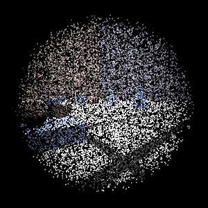
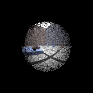
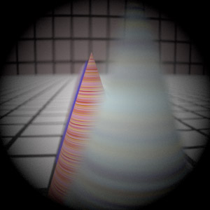
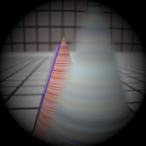
I chose to have the film plane start at z = 0 and have the ray travel along the positive z axis. Lens elements are lined up accordingly. I use ConcentricSampleDisk to sample on the entire back face of the back lens, and trace the rays through the stack. Weighting returned is the (A/Z2) * (cos4 theta) given in the paper unless the ray is blocked in which case it is 0. While tracing the lens, I noticed some lens elements with refraction index of 0 (like the aperture), I just assumed that the space behind the aperture was air, and used 1 instead (for all 0's).
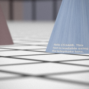
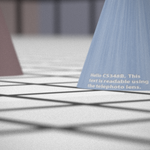
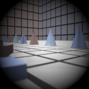
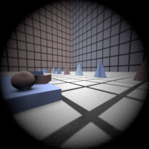
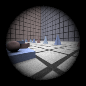
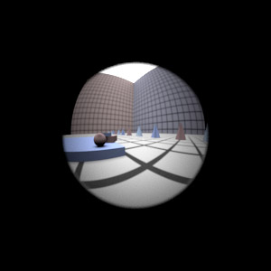
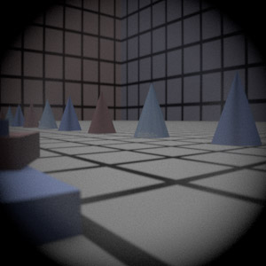
Final Images Rendered with 512 samples per pixel
|
My Implementation |
Reference |
Telephoto |
|
|
Double Gausss |
|
|
Wide Angle |
|
|
Fisheye |
|
|
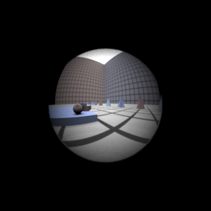
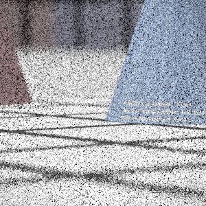
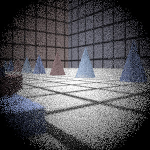
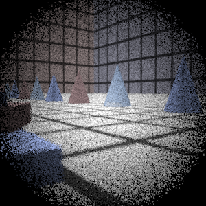
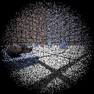
Final Images Rendered with 4 samples per pixel
|
My Implementation |
Reference |
Telephoto |
|
|
Double Gausss |
|
|
Wide Angle |
|
|
Fisheye |
|
|
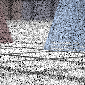
Experiment with Exposure
Image with aperture full open |
Image with half radius aperture |
|
|
Observation and Explanation
......
Autofocus Simulation
Description of implementation approach and comments
I used the Modified Laplacian described in the Nayer paper as a measure of how focused the image was. For the intensity of a pixel, I just used the sum of the RGB values. As the autofocus regions weren't very large, I simply calclated the MLP for the entire autofocus region (rather than do windows of 3 or 5 pixels). I used a step size of one in the mlp calculation, and this seemed to work pretty well.
I began by first calculating the focal distance of the lens system and beginning my search there. This makes sense because in a real camera system, the film plane must be behind the focal point. This method had several positive side effects. 1) I could avoid most of the high SML values that occur when the film distance is less than the focal distance. 2) I could speed up my search by not searching all those values.
Calculating the focal distance was somewhat annoying as it required tracing rays from objects space into the lens (opposite of the way we were doing in part 1). But by doing shooting rays with direction (0,0,1) through the system and then calculating the intersection of the resulting ray with the z axis, I could determine the focal distance.
The search proceeded from filmDist = focalDist in somewhat large steps along the filmDist (the constant FILMSTEP -- set to 4 in my implementation) and searches for a peak. A peak is defined here as 3 adjcaent MLP values where the middle one is larger than both its left and right neighbors. Using this initial algorithm, I encountered many false positives, as the MLP values had many little humps. Fortunately, the focused peak was always significantly larger than the unfocused one (and also very thin). So in order to avoid false positives, I found the ratio of the peak with its two neighbors. The ratio of the 2 neighbors to the peak must be less than a certain threshhold value in order for me to accept it as the actual focuses point. So peaks that were too close in magnitude to its neighbors were discarded. This makes sense given that the peaks are very large and very sharp.
Then given this range (from lower neighbor to upper neighbor), I perform another search over the smaller range (with step SMALLSTEP -- set to 0.6) to get a more accurate filmDist that produces the sharpest image. I use a similar search to the one above, searching for a peak. However, even in such a small range there are false positives, so I still use a threshold value for the ratio of the peak to its neighbors. I can be conservative in my approach (avoid false positives at all costs), because I also keep a maxSML value which tracks the maximum in the range. So if no peak is found which satisfies the threshold, the true peak is still found because it will be the max value in the range.
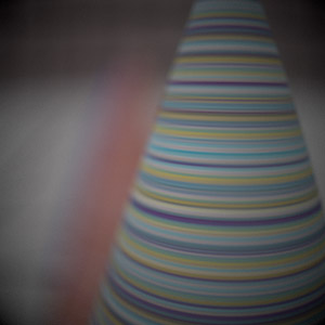
Final Images Rendered with 512 samples per pixel
|
Adjusted film distance |
My Implementation |
Reference |
Double Gausss 1 |
62.1 mm |
|
|
Double Gausss 2 |
39.7 mm |
|
|
Telephoto |
117.1 mm |
|
|
Any Extras
...... Go ahead and drop in any other cool images you created here .....
