Assignment 3 Camera Simulation
Julie Tung
Date submitted: ?? May 2006
Code emailed: ?? May 2006
Compound Lens Simulator
Description of implementation approach and comments
After reading the lens data into a vector, I precomputed certain calculations for each lens (the z-index, the zMin and the zMax, etc.) so that they would not have to be computed each time whenever GenerateRay was called. I also computed the ratio by which the raster coordinates and the film coordinates are related (by dividing the given film diagonal (mm) with the diagonal calculated using the film's pixel resolution (pixels).
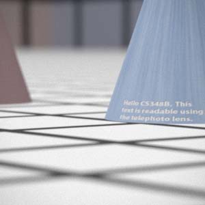
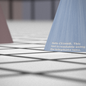
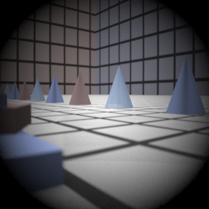
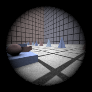
In GenerateRay, my algorithm works by converting the sample x and y coordinates into film coordinates and then choosing a point on the aperture of the backmost lens as the destination for that ray. I then pass the ray into the lens system, where for each lens, I calculate the refraction. To do this, I have to find each ray-lens intersection, which is done by modeling each lens as a partial sphere. Hence I perform ray-sphere intersection and use a z-min and z-max value in order to ensure that the intersection that I find will actually intersect the aperture of that lens. The ray is then refracted using a form of Snell's law (the vector form that can be found on Wikipedia). For the aperture stop, the effective aperture diameter is the parameter taken from the PBRT file. Here, I just perform a ray-plane intersection to make sure that the ray does not get stopped by the aperture, and I simulate the materials on either side of the aperture to be air (with a refractive index of 1). Any rays that are stopped anywhere along the lens system are given a weight of 0. All other rays have their weights calculated using the formula found in the Kolb paper. The area used is the area of the aperture of the backmost lens, the distance is the length between that aperture and the film plane, and the cosine is found by taking a dot product of the original angle of the ray with the z-axis.
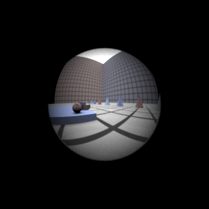
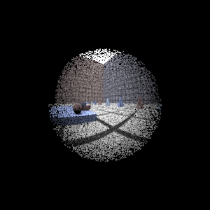
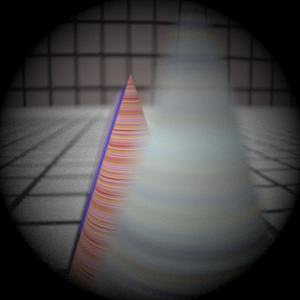
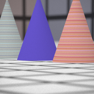
Final Images Rendered with 512 samples per pixel
|
My Implementation |
Reference |
|
|
|
Double Gausss |
|
|
Wide Angle |
|
|
Fisheye |
|
|
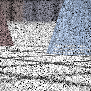
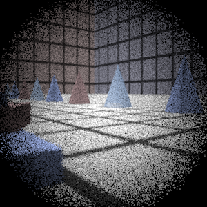
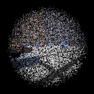
Final Images Rendered with 4 samples per pixel
|
My Implementation |
Reference |
Telephoto |
|
|
Double Gausss |
|
|
Wide Angle |
|
|
Fisheye |
|
|
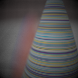
Experiment with Exposure
Image with aperture full open |
Image with half radius aperture |
|
|
Observation and Explanation
......
Autofocus Simulation
Description of implementation approach and comments
In order to implement autofocus, my first step was to calculate the focal length of the given lens system. The focal length is defined to be the distance between the lens system and the focal point, where parallel rays coming from the world (representing rays coming from infinity) into the lens would converge. I calculate this by simulating parallel rays coming in and traversing the lens system backwards, and then calculating the intersection between these rays (after they've been refracted) and the z-axis. I do this by trying a small number of sample points in the world; if I do not successfully calculate the focal length, then I just start my search at zero.
To find the optimal filmdistance, I used the Sum-Modified Laplacian as the focus measure function, as given in the suggested paper. My algorithm for evaluating the focus of a particular filmdistance would collect the RGB values on a CameraSensor, and then it would iterate through the pixel area, calculating the SML with a step size of 1 and using (R+G+B)/3 as the intensity formula. The SML is then the sum of all the ML values of the pixels in the area. I use the SML directly as a measure of the focus, because the SML acts as an edge detector, so high values are correlated with more precise edges (hence an in-focus image). The task then is to find the peak SML value and use the filmdistance that it corresponds to. Starting from the focal length as the minimum filmdistance value being tested, I try increasing filmdistances, recording the highest peak I've seen so far. I ended up using a step size of 5 mm in this step; although I tried out larger values (9, 10 and higher), I opted not to use them because the peaks are very narrow and are easily missed when using those larger ranges.
Final Images Rendered with 512 samples per pixel
|
Adjusted film distance |
My Implementation |
Reference |
Double Gausss 1 |
mm |
|
|
Double Gausss 2 |
mm |
|
|
Telephoto |
mm |
|
|
Any Extras
...... Go ahead and drop in any other cool images you created here .....
