Final Project: The Caterpillar
Tarang Vaish & Shradha Budhiraja
Inspiration
Project Goals:
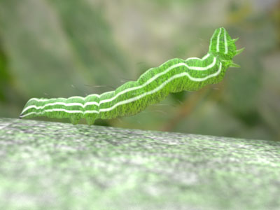
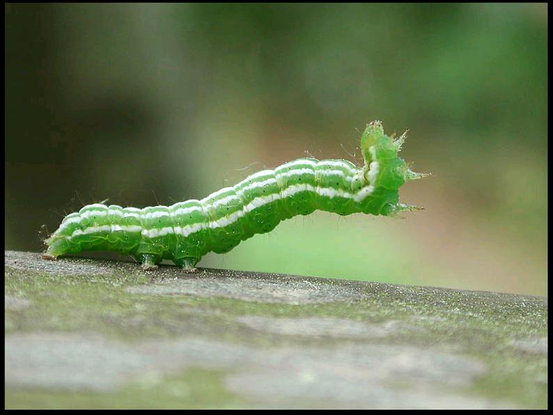
The inspiration for our final project idea was taken from one of the images we found on the internet. While we were awed by the look of the image, we were also overtaken by the intricate details present in the image. Some of the features which were most striking: - A long segmented body that has band-like repeating patterns. - Translucent skin/body reflecting the material within. - Non-uniform scattering within different parts of the body. - Spiny bristles and long hair covering the body of the caterpillar. - Tiny hair around the body forming a slight halo. - White texture on the body. - Depth of field simulated by the camera in the background. - Floor/Bark on which the caterpillar rests.
Techniques used:
1. Subsurface Scattering – We implemented subsurface scattering using “A Rapid Hierarchical Rendering Technique for Translucent Materials”, Henrik Jensen & Juan Buhler. The earlier paper by Jensen et al. [2001] on subsurface scattering compute the contribution from multiple scattering by sampling the irradiance at the material surface and evaluating the diffusion approximation – in effect convolving the reflectance profile predicted by the diffusion approximation with the incident illumination. Even though the diffusion approximation is a very effective way of approximating multiple scattering, this sampling technique becomes expensive for highly translucent materials. The reason for this is that the sampled surface area grows and needs more samples as the material becomes more translucent.
The key idea for making this process faster is to decouple the computation of irradiance from the evaluation of the diffusion approximation. This makes it possible to reuse irradiance samples for different evaluations of the diffusion equation. For this purpose, Jensen introduces a two-pass approach in which the first pass consists computing the irradiance at selected points on the surface, and the second pass is evaluating the diffusion approximation using the precomputed irradiance values. For the second pass the decreasing importance of distant samples is exploited and a rapid hierarchical integration technique is used.
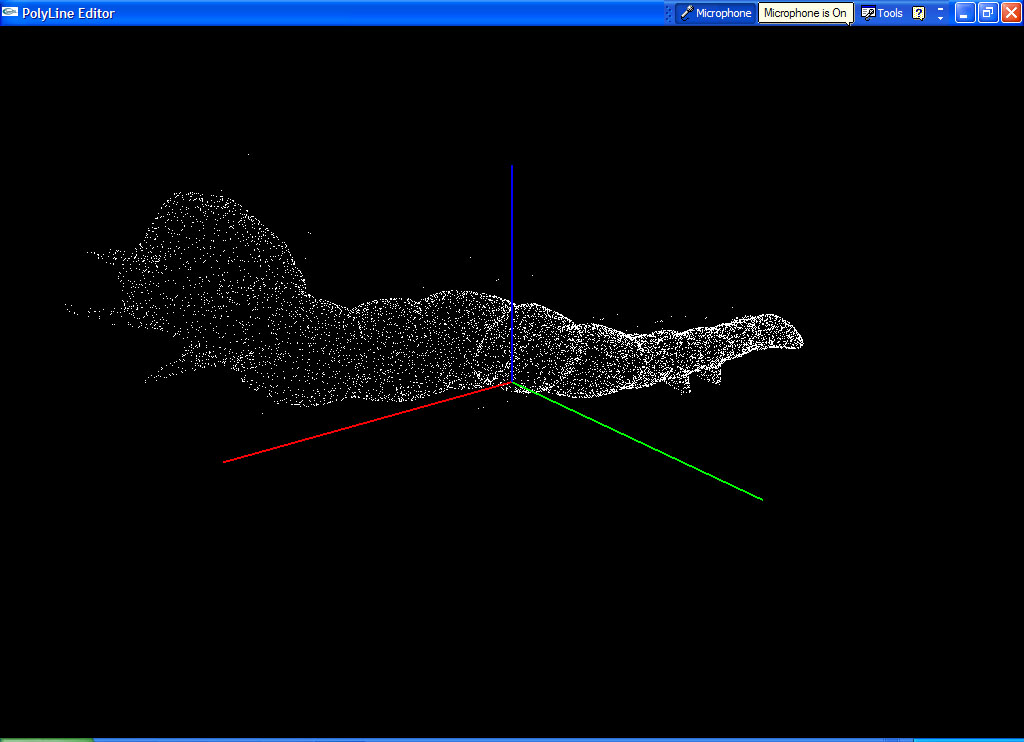
2. Photon Mapping - For the first pass, we used photon mapping to generate the samples on the surface. Scatter photons are generated along with direct and indirect photons. The scatter photons are stored in an octree which are later accessed to calculate luminance values at different points on the surface.
The visualization of the scatter photons can be seen below:
3. ==== Procedural generation of floor surface: ==== The floor surface was generated using fissure and color maps and applying bump mapping.
Special effects:
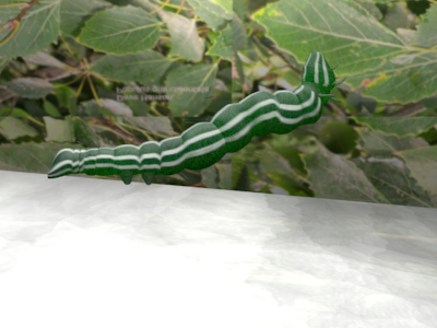
1. ==== Non-uniform scattering within the body material: ==== The subsurface scattering algorithms given by Jensen implement uniform subsurface scattering as can be seen in materials like marble, milk, etc. After implementing the basic material, we made variations to the algorithm to bring about the non-uniformity that we observed in the material of the caterpillar skin.

Non-uniformity was introduced by varying the parameters of subsurface scattering. In Jensen’s paper, the diffusion approximation is evaluated by performing a hierarchical summation of the contribution from all the irradiance samples. We modified this by performing a weighted sum of the different samples in the tree. The weights are generated randomly at different sample locations. This provides a varying proportion of scattering throughout the body. The fall of a single photon was computed using diffusion approximation. Also, the color for the caterpillar was experimented by varying the absorption and scattering parameters, σa and σ`s for different values of green until we found a value that closely matched the color of the caterpillar skin.
|
|
|
||
2. ==== Halo surrounding the body to give tiny hair-like appearance: ==== We first tried to implement the fur algorithm by Kajiya to grow fur around the body of the caterpillar. However, the appearance didn’t look realistic and was more dense than required. We decided to instead, change the scattering algorithm to accommodate this feature. To give a halo around the body, we deposited the photons a layer below the surface of the skin and not on the surface as the algorithm usually does. This gave a dark layer before the actual scattering began which gives a slimy/tiny hair look.
3. ==== Texture mapping: ==== As the usual subsurface scattering algorithm addresses materials that are non-textured, we combined the usual photon mapping with the scattering algorithm. At the surface, the direct and indirect photons were deposited. These photons were stored in a Kd-tree. The luminance value for the surface photons was calculated by taking an area average over a small circular region covering neighboring photons. By combining the two methods, we were able to blend in the texture on the caterpillar surface.
|
|
|
4. ==== Translucency/Transparency: ==== We used the ‘uber’ material for the skin of the caterpillar. We used the class parameters of this material to define a scattering/non-scattering material, give the basic BRDF and scattering properties of the material. Different parts of the caterpillar like body, legs, hair and tentacles were made separate components so that we could assign different values to the above mentioned properties.
5. ==== Depth of field: ==== A depth of field was created using a perspective camera. We also tried using the realistic camera implemented in class. However, we found that the perspective camera gave the best results for the depth of field.

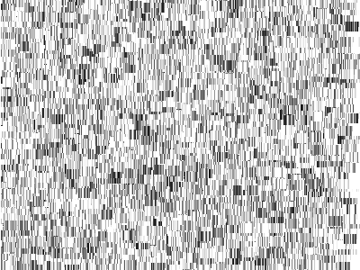
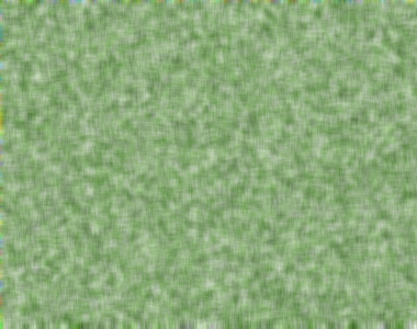
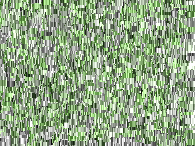
6. ==== Floor/Bark: ==== The floor was procedurally generated using fissure maps. The pixels were assigned a uniform distribution of gray intensities values. At every pixel, it was decided whether to generate a fissure or not. The decision was made based on the probability of the pixel. To create the fissure, a window of 30X15 around the pixel was taken, and the values of pixels in this window were altered using a random number. A similar algorithm was used to generate a color map consisting of green and white colors. These maps were then combined to generate a texture for the floor which was scaled and bump-mapped.
|
|
|
||
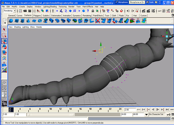
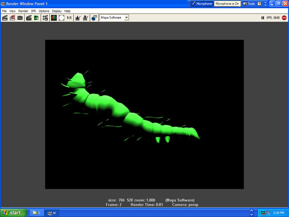
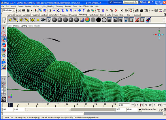
7. === Model: ==== The model of the caterpillar was made in Maya7.0. The cylindrical segments were made by using NURBS surfaces. The different components and properties of NURBS modeling were used to modify the basic surfaces. We then used the Maya-PBRT renderer to generate the pbrt file.
|
|
|
||
8. === Lighting: === We used an area light source for the lighting. We tried different types of lighting, like spot light, direction light, etc. However, to have an appropriate number and energy of photons, we found that an area light was most suitable. We also tried an environment map as a light source, but it generated photons from all directions and generating a large number of photons was infeasible from this method as it took a long time to converge.
Challenges faced:
1. The biggest challenge was to match the color of the caterpillar along with non-uniform scattering within the caterpillar's body.
2. We were also limited due to Maya's polygonal meshing. when we tried to increase the triangulation to make the model look smoother and realistic, the pbrt file became increasingly large (500 MB). Due to this limitation, the final model looks a little tesselated and unrealistic.
3. We wanted to have veins as visible from within the body in the real image. However, we did not have enough time to implement that.
Conclusion:
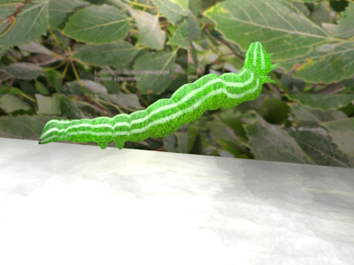
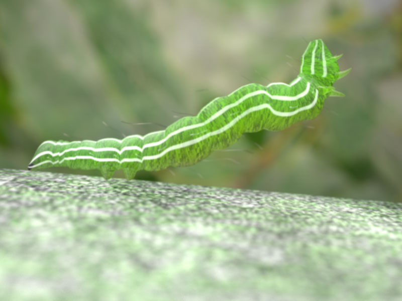
We finally got a close match of the rendered and the actual image. These can be seen as below. We rendered the image with different parameters of: - resolution - number of photons - number of samples per pixel( 64, 128, 256).
Final Images:
|
|
|
Statistics
400 X 300 Image, 64 samples per pixel.
-Shooting Photons – 37.6s -Rendering – 3362.3s -Camera:
- -Camera Rays Traced - 7.860M
-Geometry
- -Total shapes created - 35.5k -Triangle Ray Intersections - 16.582M:106.682M (15.54%) -Triangles created - 35.5k
800 X 600 Image, 64 samples per pixel.
-Shooting Photons – 37.6s -Rendering – 14997.1s -Camera:
- -Camera Rays Traced - 31.079M
-Geometry
- -Total shapes created - 35.5k -Triangle Ray Intersections - 64.586M:415.983M (15.53%) -Triangles created - 35.5k
