* This link will take you to the drawings for this building. There appears to be no way to link to the main record about the building. To reach it, go to the HABS search page and enter the building name.

Web page and text by Marc Levoy
January 24, 2001
updated March 19, 2002
Since 1933, the Historic American Buildings Survey - a division of the National Park Service - has been sending survey teams out into the field to record historically important American buildings. I studied architecture in college, and in the summer of 1974 I joined one of these teams as a student intern. The supervisor of our team was Michael Tomlan, who is now on the faculty of the Department of City and Regional Planning at Cornell University. Our assignment was to measure, photograph, and draw several antebellum (pre-civil war) homes and buildings in rural eastern Tennessee. During the course of the summer, our team measured and drew roughly a half-dozen buildings. Here are two of them.
|
|
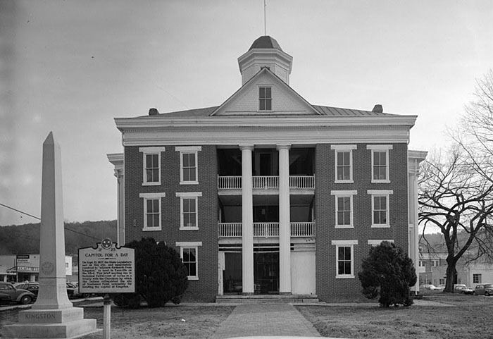
The first building we measured that summer was the
Roane County Courthouse*. in Kingston, Tennessee. Built in
1854, it still serves as the county courthouse for Roane County (or at least it
did in 1974). While in the field, our team of about five people took pictures,
made measurements, interviewed residents, and performed other historical
research. Returning to our temporary studio at the University of Tennessee in
Knoxville, we began converting our measurements into plans, elevations, and
section drawings.
* This link will take you to the drawings for this building. There appears to be no way to link to the main record about the building. To reach it, go to the HABS search page and enter the building name. |
|
|
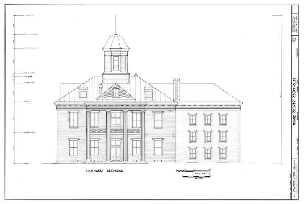
Here is a side elevation I made of the courthouse. Click here to see the drawing at 100 dpi, which is life size if you are using a 1280 x 1024 pixel, 19 inch display. (Warning, this image is big!) This is the first drawing I made that summer, and my penmanship was frankly not that great. (My drawings of Rural Mount, made at the end of the summer, were better.) Drawings were done on "2000-year vellum", so-called because it is designed to last that long. Our drawing instruments were mechanical "Rapidograph" pens. Note the variations in line width used to distinguish foreground from background features and to highlight silhouettes. HABS permitted us to use pen tips whose gauge ranged from "3" (very fat) to a special, diamond-tipped "0000" (very very skinny). On this drawing, these delicate and expensive styluses were used only for the brickwork of the rightmost wing. Before my "digerati" colleagues scoff at this quaint technology, let them try to convince me that any computer data they have created will last 2000 years. |
|
|
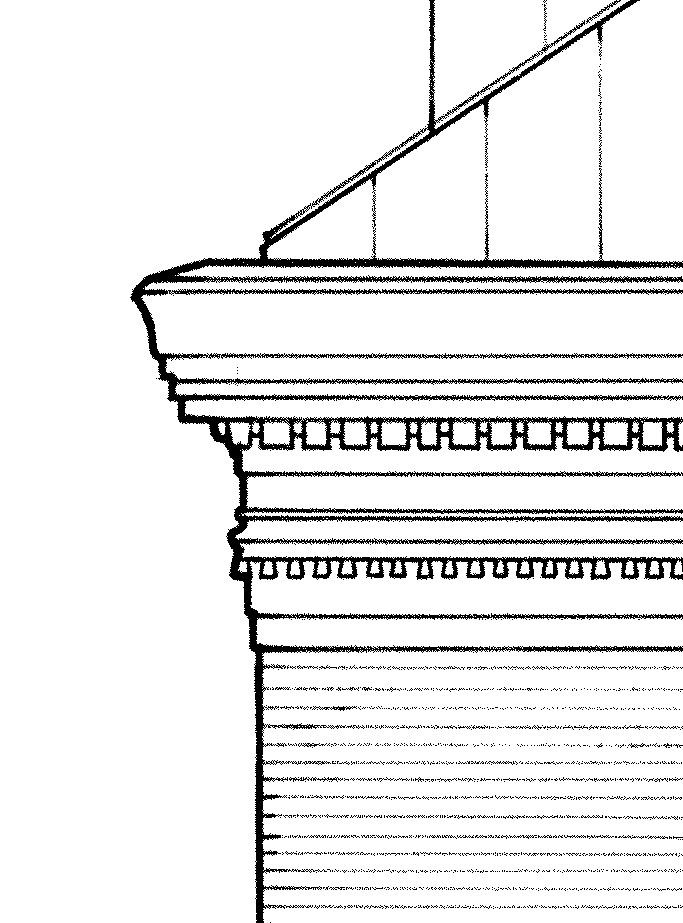
HABS's rule about accuracy was that every line on these drawings was supposed to represent a measured feature of the building. This rule applied even to the spacing between brick courses and the profiles of column capitals. If recorded accurately, these details can be used by future architectural historians as clues for tracing the career of particular architects or the proliferation of particular architectural pattern books. To measure these objects, we gently pressed a handheld comb with slidable metal teeth against the building, so that the comb took on the object's profile, then we traced the profile onto paper and reduced it xerographically. Performing these measurements was easy for the balustrade visible at lower-right. It wasn't so easy for the cornice of the building (at center-left), because it involved hanging over the edge of the roof 30 feet above the ground. I was the lightest member of the group and too young to realize I was mortal, so I ended up with this task. Perhaps it was this experience that motivated me to work on 3D laser scanning 20 years later! |
|
|
Want to check out HABS's digitization technology? Here is a small section of the drawing at the maximum resolution available from their web site - 400 dpi (bilevel). (At this resolution, which is 4 x life size, the drawing is an image 14,452 pixels wide.) Frankly, it looks a bit noisy to me. Uh oh, maybe that 2000-year vellum had begun to degrade before they digitized it! |
|
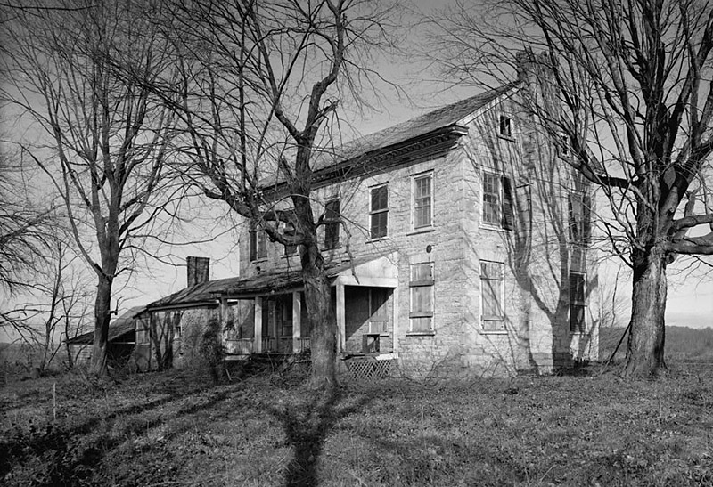
Another building our team measured during the summer of 1974 was Rural Mount, near Morristown, Tennessee. It was built in 1799, reputedly for Joseph Hamilton, who was instrumental in founding of the state of Tennessee. At left is a general view of the house. Although it was abandoned when we photographed and measured it, the stonework and interior woodwork was still in excellent condition. |
|
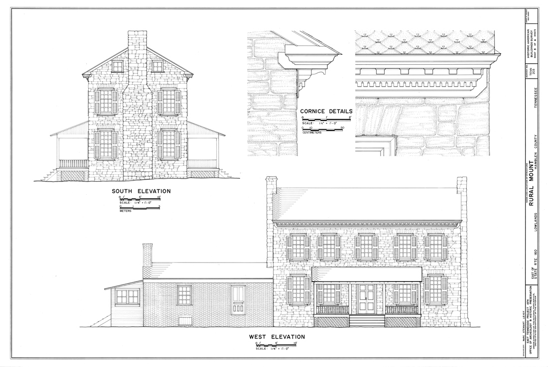
Of the six drawings of this building that were made by our team, I drafted two of them. The first of these shows some exterior elevations of the house. Click here to see the drawing at 100 dpi. Following HABS's rule (explained earlier) about accuracy, every stone on these drawings is correctly placed and sized. I accomplished this by working from photographs of the building's walls, a slow and laborious process. Of particular importance are the quoins - the stones that line the outside corners of the building - because they give us a clue about the identity of the stonemason. |

|
Several months had elapsed since I drew the Roane County Courthouse (see above), and my technical proficiency had improved considerably. Here is a blowup of the cornice details from the foregoing elevation drawing. I am particularly proud of this drawing, which the National Park Service has reproduced in a number of general HABS publications about the recording of America's architectural heritage. |

|
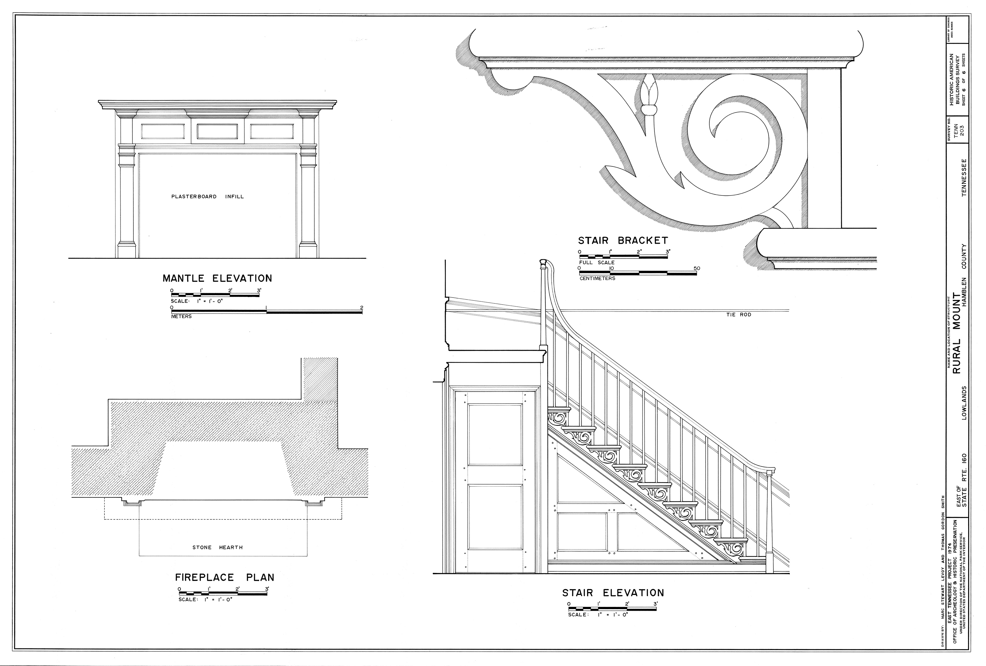
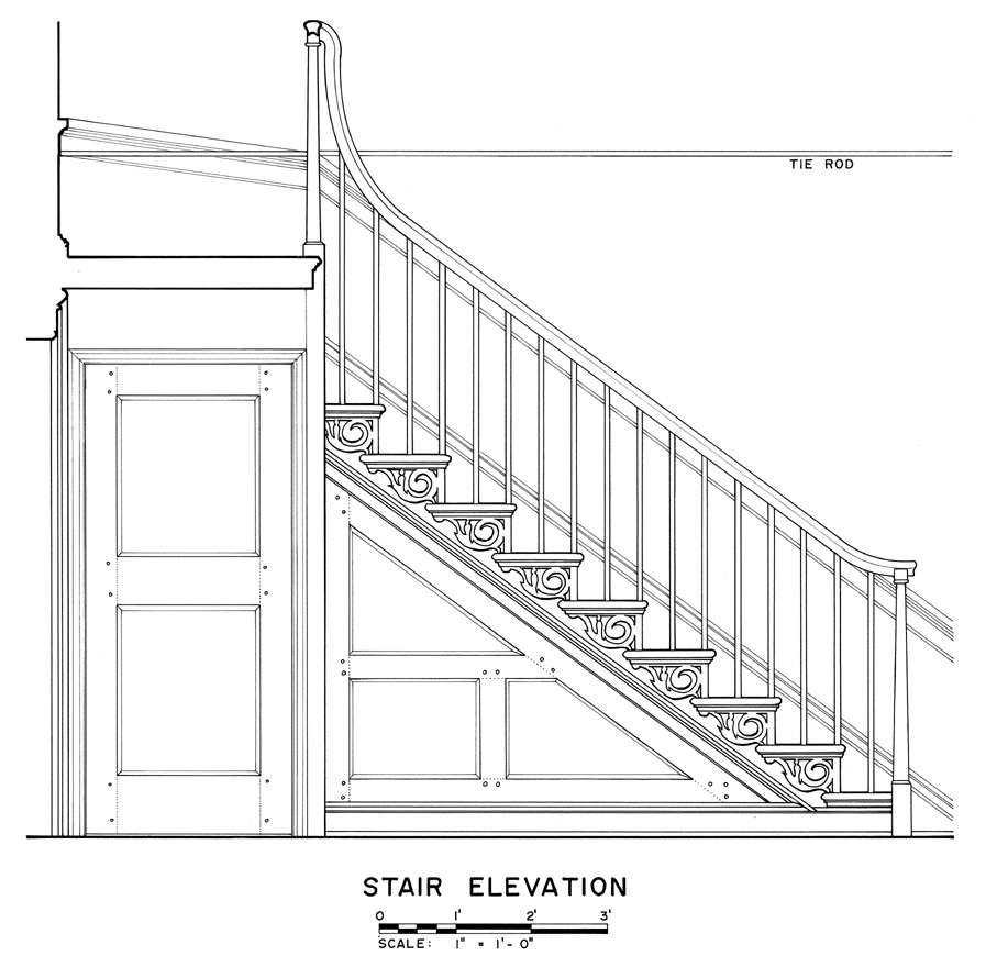
The other drawing I made of Rural Mount showed some of the interior details, including the main staircase and one of its decorative brackets. Click here to see the drawing at 100 dpi, and click here for a blowup of just the stair elevation. The brackets are interesting because they resemble designs from builder's handbooks of the late 18th century. As such, they are one of the elements used to verify the date of construction of the house. |
Nowadays, a computer model of this building could be made using a 3D modeling package and time-of-flight laser scan data, and the stonework could be texture mapped onto the model from photographs (except where occluded by trees). Replacing these drawings with computer renderings is a different story. Like any technical illustration, these drawings contain selective abstractions, simplifications, and emphasis. Although the computer graphics research community has made good progress in non-photorealistic rendering techniques, making effective technical illustrations automatically is still an open problem.