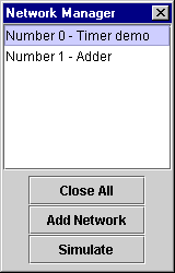

Initially, the list of networks will be empty. You want to create a new network to work with, so click the "Add Network" button of the Network Manager. You should see a new blank network appear in the upper left corner of the SimPLC window, and it will be listed in the Network Manager.
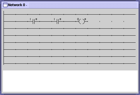
Try building a simple circuit in this new network. You can start building a simple AND logic gate by dragging components from the Component Bin onto your network until it looks like this:

Now, you need to specify which input lines control each of the switches, and which output line will be written to by the output coil. The role of these input and output lines will become clear once you start simulating your circuits; for now, just think of them as your circuit's link to the outside world. There are five different kinds of lines that circuit components can use: regular inputs, momentary inputs, outputs, flags, and registers. For now, we only need to work with regular inputs and outputs.
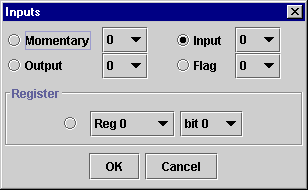
Click the right-mouse-button on the second switch in your network, and choose edit from the menu that appears. You should then see a dialog box like this:

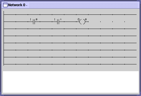
In this example, you can see that right now this switch is controlled by input line 0. Go ahead and change it to use input line 1, instead, and click OK. Your network should now look like this:

Notice that the number in the right hand corner above the switch changed from 0 to 1. The letter I on the upper left corner indicates that the switch is using an input line, and the number in the upper right corner indicates which particular input line is used.
You've now built an AND gate. Move on to the next section on simulation to test it.
Next: Simulating a Circuit