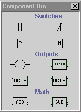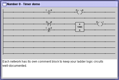

Components are connected to one another and assembled into circuits by using the mouse to drag them from the Component Bin into a rectangular grid called a network:

As you can see, a network in SimPLC is just an 8x11 grid of nodes, or slots where components can be placed. Some components, like switches and output coils, only occupy one node in the network. Others, like the timer shown above, make take up two or more nodes in the network. Each row of the network is called a rung. The long vertical line connecting all the rungs at the left hand side is the power rail, which supplies power to the network. Power flows across a rung from left to right until an open switch or other obstacle is reached, after which no further power flows on the right hand side of the switch. Normally, power cannot flow between two rungs. However, vertical shorts can be placed between two adjacent rungs to allow power to flow between them at that point.
Next: Designing a Circuit