Lightfield Camera Simulation
2nd prize winner of the Rendering Competition: CS 348b (2014)
Team: Zahid Hossain, Adam S. Backer, Yanlin Chen
Instructor: Dr. Matt Pharr
( This is not the final report ! )
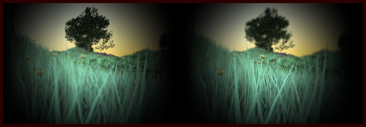 |
| Fig 1. The final submission image (captured with a single element spherical lens) that demonstrates after the fact refocusing, spherical distortion and vignetting from lightfield imaging. The left panel is focused at the far tree while the right image is focused on the near flower. Note how the grass blades near the edge of the vignette, due to spherical lens distortion, are not focused at the same time as the flower though they belong to the same $z$ plane. |
| Video demonstrating after the fact refocusing, multiple view point rendering and vignetting effects of lightfield imaging. Note that the multi viewpoint scenes (when the camera seems to pan around) are noisier than refocused images. |
 |
| Fig 2. Microlens array placement. Courtesy of Ng et.al. [2] |
Lightfield Data
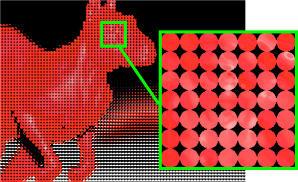 |
| (a) Lenslet format |
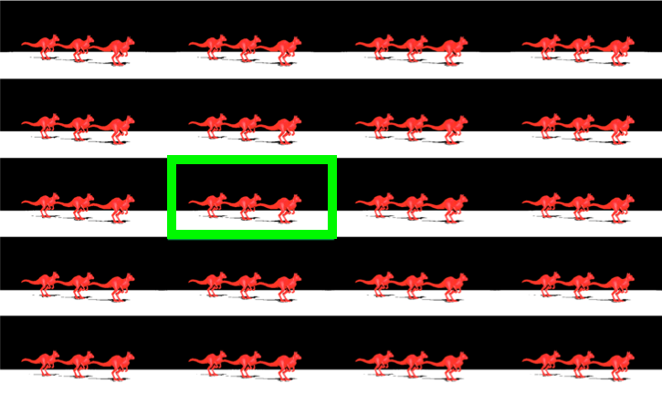 |
| (b) Subaperture format |
| Fig 3. Raw lightfield image. (a) Data in lenslet format, where each circle is a point sample of $(s,t)$ while the pixels within the circle are the point samples of $(u,v)$. (b) Data in subaperture format, where pixels in each subaperture image (marked by a green box) are taken from the same $(u,v)$ coordinate from every lenslet image in (a). Both these format essentially stores the same information. |
Refocusing
In this project we were only interested in computing a synthetic focus plane $s'$ while keeping the main lens $u$ and microlens plane $s$ intact as illustrated in Figure 4. Now, in order to shade a synthetic pixel at location $s'$ we need to sample the captured lightfield by tracing rays from every point $u$ on the main lens that passes through $s'$. Therefore, the first step is to compute the intersection $s$ given $s'$, $u$ and $\alpha$ - which is the distance of the synthetic plane from the main lens as a fraction of the sensor distance $F$. This intersection, after simplifying equations of Ng et.al [2], is given by: $$ s = \frac{1}{\alpha} \left( s' - (1-\alpha) u \right) $$ Once this intersection of $s$ is established, the irradiance of a synthetic pixel $E(s',t')$ is given by the following integral -- where $L(u,v,s,t)$ is the captured light field: $$ E(s',t') = \int_{u,v} L( u,v, \frac{1}{\alpha} \left( s' - (1-\alpha) u \right), \frac{1}{\alpha} \left( t' - (1-\alpha) v \right) dudv $$ |
| Fig 4. Synthetic refocusing is performed at an arbitrary plane $s'$ by tracing rays, through a given synthetic pixel, that pass through the subaperture spanned by $u$ from the main lens to the captured lightfield plane $s$. The distance of the synthetic plane from the main lens is parameterized by $\alpha$ which is the fraction of total distance from the main lens to the microlens array. |
We took off the $1/\alpha$ term from the above refocusing equation to get rid of the scaling effect from our synthetically refocused image. This is equivalent to sampling the synthetic plane more densely as we move it closer to the main lens thus keeping the dimensions of the rendered image (in pixels) the same. We eventually used the following modified integral to compute our final refocused image $$ E(s',t') = \int_{u,v} L( u,v, \left( s' - (1-\alpha) u \right), \left( t' - (1-\alpha) v \right) dudv $$
Since the intersection of $s,t$ and the integrand $u,v$ are all continuous variables we performed interpolation on the discrete lightfield $L(u,v,s,t)$ to convert it into a continuous function. For this we used three different interpolation techniques; i) Nearest Neighbor (NN) in all 4 dimensions, ii) Linear interpolation in $(s,t)$ but NN in $(u,v)$ and iii) Linear interpolation in all 4 dimensions. We noticed a greater reduction of artifacts as we linearly interpolated along $(s,t)$ dimensions alone. Figure 5 shows the effect of these interpolation
techniques.
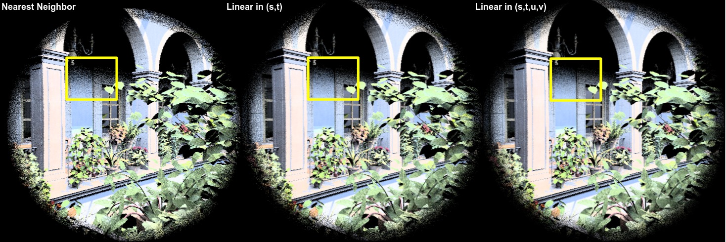
Fig 5. Effect of different interpolation techniques. Linear interpolation along $(s,t)$ alone seemed to have more significant effect than $(u,v)$
Results
Refocusing
 |
| Fig 6. Test scene to demonstrate refocusing algorithm. One killeroo is brought to focus at a time. |
Playing with depth map
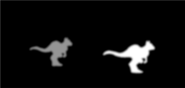
The synthetic focus plane being virtual we were able to make the $\alpha$ parameter vary over the focus plane thus simulating many interesting imaging phenomena, e.g. tilt-shift (see Figure 7) to generate an all-in-focus image, and selective focusing (see Figure 8) by hand drawing depth maps. |
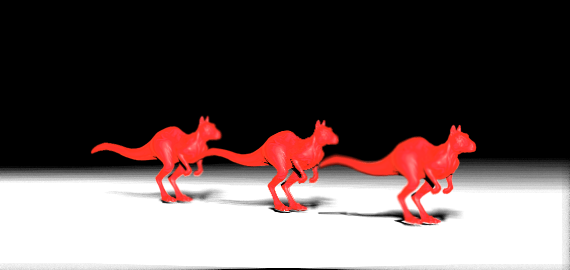 |
| Fig 7. Synthetic tilt shift imaging to produce an all-in-focus image. The left image is a hand drawn depth map that encodes varying $\alpha$ over the synthetic focus plane. The right image is the refocused image that has all the three killeroos focused at the same time. | |
 |
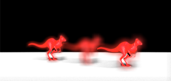 |
| Fig 8. Selective focusing by hand drawing depth map. The left image is the depth map and the right image is a resultant refocused image where the farthest and the nearest killeroos are in focus while the middle one is not. This is unattainable in a conventional camera. | |
Impossible Macro Photography
| Video demonstrating objects placed closer than one focal distance can still be brought to focus with lightfield imaging. |
Extra Scene and Spherical Aberration
Here we captured lightfield using the stock San Miguel scene (sanmiguel_cam20.pbrt) that has a lot of depth complexity. The following video demonstrates the same refocusing and multiple viewpoint rendering as well as Spherical Aberration due to a single spherical lens element. Note how the leaves along the edge of the vignette are brought to focus earlier than the ones in the center of the scene even though they reside approximately on the same $z$ plane. This is because light rays that pass through the edge of a spherical lens converge earlier than the focal distance. It is also interesting to note how the subaperture images, while rendering multi viewpoint shots, tend to be noisier than the refocused images. This is because less light rays are integrated during subaperture image reconstruction.| Refocusing and multiple viewpoint rendering with the stock San-Miguel scene (sanmiguel_cam20.pbrt). For this we used a single element spherical lens that suffers from spherical aberration. The leaves along the vignette edge are focused earlier then the ones in the middle, though they are approximately on the same $z$ plane, as we move our focus closer to the nearer planes. Also note, how the subaperture images while generating multi viewpoint scenes are noiser than the full aperture refocused image. |
Final Remarks
We found lightfield imaging to be an interesting method for photography as one never has to worry about setting up a capture but simply capture the precious moment that may not last more than a split second. One of the challenges in this space is the reduced resolution of the refocused image due to fitting the angular information into the same image sensor real estate. However, lots of work along synthesizing super-resolution image from a lightfield are still in progress [3,4], and it has already been shown that the information in a lightfield is very rich and the final refocused image resolution does not always necessarily gets divided by the angular resolution.
References
[1] Kolb, Craig, Don Mitchell, and Pat Hanrahan. "A realistic camera model for computer graphics." Proceedings of the 22nd annual conference on Computer graphics and interactive techniques. ACM, 1995.[2] Ng, Ren, et al. "Light field photography with a hand-held plenoptic camera." Computer Science Technical Report CSTR 2.11 (2005).
[3] Venkataraman, Kartik, et al. "PiCam: an ultra-thin high performance monolithic camera array." ACM Transactions on Graphics (TOG) 32.6 (2013): 166.
[4] Bishop, Tom E., Sara Zanetti, and Paolo Favaro. "Light field superresolution." Computational Photography (ICCP), 2009 IEEE International Conference on. IEEE, 2009.