CS348b Final Project: Ray-tracing Interference and Diffraction
Douglas V. Johnston dvj@cs.stanford.edu
Paul N. G. Tarjan ptarjan@cs.stanford.edu
Abstract
Although inherently a wave phenomena, diffraction can be implemented in a ray tracer by taking advantage of a combination of Geometric Diffraction Theory and the Huygens'-Fresnel Principle. In this paper we show how to implement interference and diffraction in a computationally tractable manner, while retaining the properties of the full volume integration solution.
Introduction
Physical reality is a goal for many ray tracing applications. The complex interaction of lighting is often one of the more challenging components for a ray tracer to render in a realistic fashion. When rendering small scenes with visible light, or when rendering long wavelengths, diffraction plays an important and often overlooked role.
Diffraction, the bending of light around objects, is a difficult phenomena to represent in the context of ray tracers[1]. Because ray tracers inherently calculate straight line paths, and only compute ray object intersections, the continuous, wave-like attributes of diffraction must be discretely approximated.
Interference is caused by light waves having a phase associated with them, not just an intensity. When two light waves hit the same object they could be in phase or out of phase, which determines how much intensity is observed at that point. Ray tracers are well suited to associate phase with each light ray, which makes creating interference patterns a minor change to most ray tracers.
We will first introduce the basic principles behind interference and diffraction, and then show a viable implementation strategy in the context of the PBRT ray tracer[4]. Finally we will show results highlighting the benefits and increased physical reality of the diffraction system described.
Interference
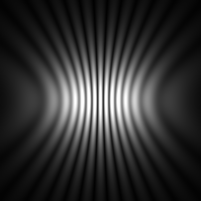
Interference of light is superposition of multiple light waves. This manifests itself as a changing intensity due to the constructive and destructive interference caused by the interaction of coherent light sources In phase waves will add their respective intensities, and out of phase waves will instead cancel.
|
|
|
|
|||
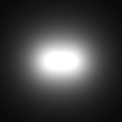
(a) Without interference |
(b) With interference |
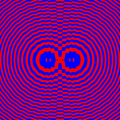
(c) Phase contours |
(d) Phase and intensity |
|||
Figure 1: Two monochromatic coherent point light sources spaced by projected onto a plane. (a) If interference is neglected, we get the same image we would expect from a macroscopic scale. (b) However, when the effects of interference are taken into account, the pattern of constructive and destructive interference becomes apparent. (c) The combined phase can be computed at each point. Red indicates a phase between 0 and , and blue between and . (d) The phase plot is shown with the proper intensities.
Most ray tracers sum two samples by just adding their intensities. This is correct if the two waves are of the same phase, but they could sum to zero if they are perfectly out of phase. This effect is only noticeable in certain situations but is nonetheless part of the real world.
In order to simulate interference, each color is stored as a complex number (compared to most ray tracers, that just store the intensity). All operations are done in the complex plane. When the sampling is completed, the final image may be written with just the length of the complex number to show the intensity as we would see it in the real world, or one can associate a coloring scheme to the phase which allows visualization of light phases (see Figure 1).
Each complex number is stored in Cartesian coordinates. This allows for quick addition which is the most common operation in the ray tracer. The final number is given in polar notation, since the amplitude corresponds to the intensity of the light, while the phase is unseen (unless using it to visualize diffraction phenomena).
Diffraction
Diffraction is a physical phenomena of all waves. A simple, everyday example of diffraction can be observed by listening to a speaker. One does not need to be in the direct path of the sound waves for the speaker to be heard. The sound will travel around a corner by bending due to diffraction. Wave-particle duality states that light is also a wave, and will bend around objects. Visible light, however, bends a relatively small amount due to its wavelength being much smaller than most objects. However, when an object's size begins to approach the size of the wavelength, the diffraction effects are readily observed and are an important effect.
The diffraction pattern for an aperture can be determined by integrating the phase and intensity of all light incident on the aperture[2]. For a circular aperture, the resulting pattern is the famous Airy disk (See figure 2).
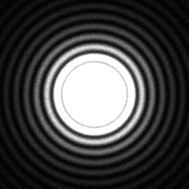 Figure 2: An area light source of radius 7000/6 shining on a diffuse plane 10000/6 away, using 1024 samples per pixel, where is the wavelength of light. This pattern is known as the Airy Disk.
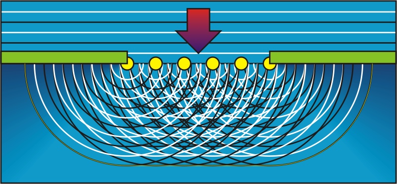 Figure 3: Huygens'-Fresnel Principle: A planer wave can be represented by point sources along the wavefront. The resulting wave can be regarded as the sum of all the secondary wave-fronts arising from the point sources.
The theory of geometric diffraction states that the bending of light can be approximated by changing the angle of a ray of light on the edge of an object. In order to compute the proper angle and phase of the redirected light, a diffraction coefficient must be computed for the material and shape. This is impractical for general objects and materials as coefficients are not easily found and must be empirically measured. Although approximations can be used about the shapes, in general, the error is unbounded.
The Huygens'-Fresnel principle states that a light wave may be represented by an infinite number of hemispherical light sources incident on the wave front. Their principle direction is normal to the wavefront facing the direction of travel. In the general case, this would involve placing light sources filling the volume of the scene. This is computationally intractable. To make this computationally feasible, we must limit the number of Huygens'-Fresnel light sources. We accomplish this by placing light sources only at the edges of objects. This is possible due to the negative interference of all light sources which are not incident on an edge as stated in the Huygens'-Fresnel theory. Hence, an aperture may be represented only by light sources around its edge. The resulting pattern is the same as if integrating over the entire area.
Babinet's principle states that a duality exists between an aperture and an opaque body of the same shaped silhouette as seen from the light source. This theory allows the rendering of opaque objects by placing light sources around their outer edge, as done for apertures. Edges are defined as point where the surface normal is orthogonal to the incident light rays. A more formal description of the computation of the edges is described in section 4.2
We use the discretized approximation of the above theory where light sources are spaced more frequently than the sampling Nyquist limit dictates.
General Implementation
PBRT, like most ray tracers has no support for the wave-like properties of light. In order to implement the physical interaction of waves in pbrt many parts of the the underlying structure need to be changed. In particular, the spectrum class must be augmented to handle phase in addition to amplitude (intensity) of light, and the light sources must support the proper bending of their rays.
Complex Valued Lighting
The spectrum class modifications to account for interference of light are handled in a rather straightforward way. Instead of a single real valued number representing the intensity of light, we use a complex valued number, which represents the amplitude and phase of the light. In order to simplify the evaluation of the complex signal, we use a Cartesian coordinate representation instead of the amplitude and phase representation. This change of coordinate systems removes the need of trigonometric evaluations when performing operations on the spectrum class.
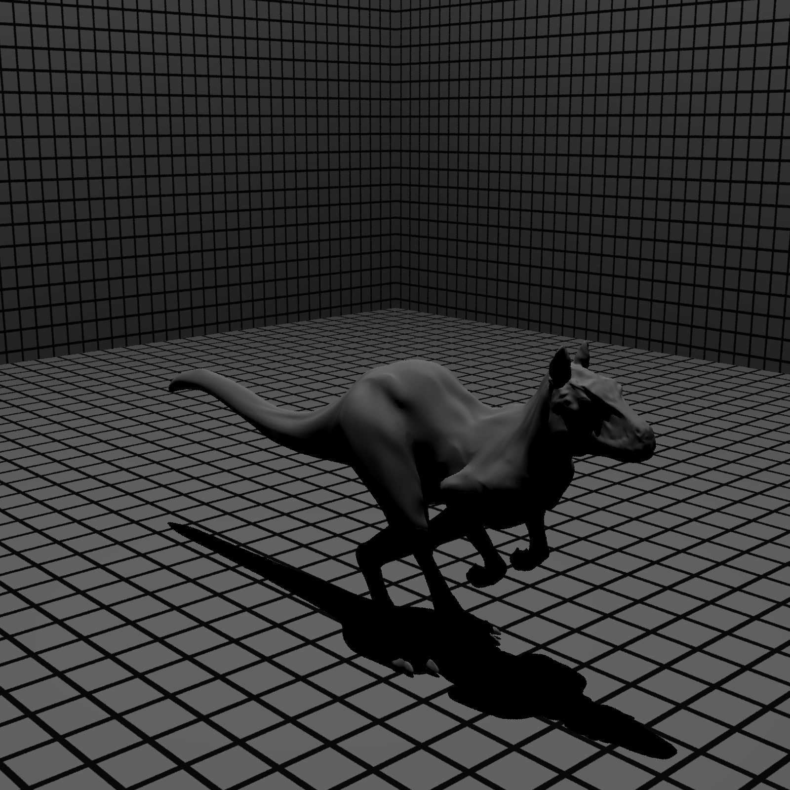
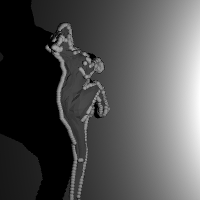 Figure 4: The shadow mask as seen from a light source shining from the side
Silhouette Edge Computation
In order to properly place the diffracted light source on the incident objects, the edge boundary must be computed for all objects. For spheres, this is computed by first finding the plane orthogonal to the ray passing from the light source through the center of the sphere, incident on the center of the sphere. Then, light sources are uniformly distributed around the circle of intersection of this plane and the sphere.
The edge boundaries of triangle meshes are slightly more complicated. For all edges, , in the triangulation, check the following: First, compute the vector mutually orthogonal to the ray passing from the light source through the center of the edge in question, and the direction of the edge. This vector represents the edge normal. A point is located a small value, , from the edge surface in the direction . If the edge is along the silhouette edge as seen from the light source, then a ray from the light source through will not intersect any of the faces incident on . This is tested by assuring a ray from the light source to plus some does not intersect the object.
Once it has been determined that an edge is part of the boundary set of edges, light source are placed along the edge, in accordance with the Huygens'-Fresnel approximation.
Results
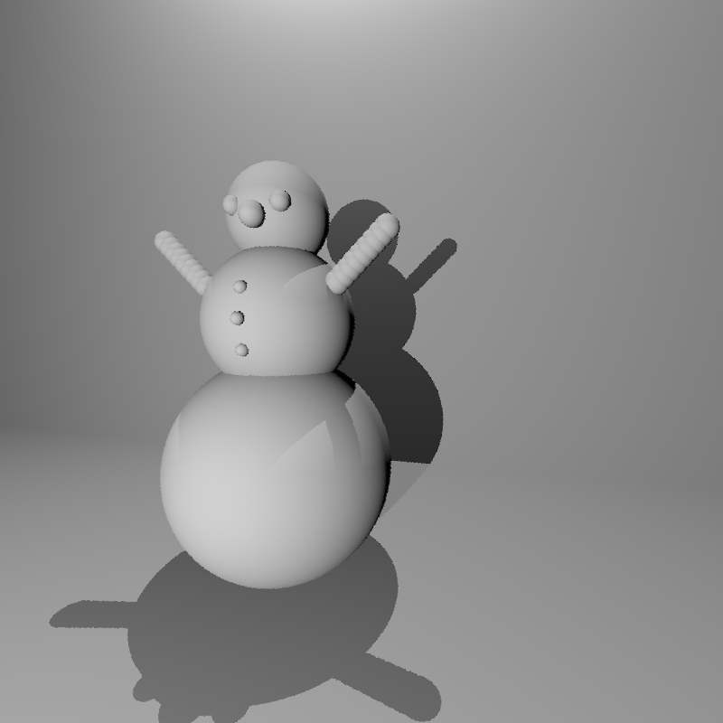
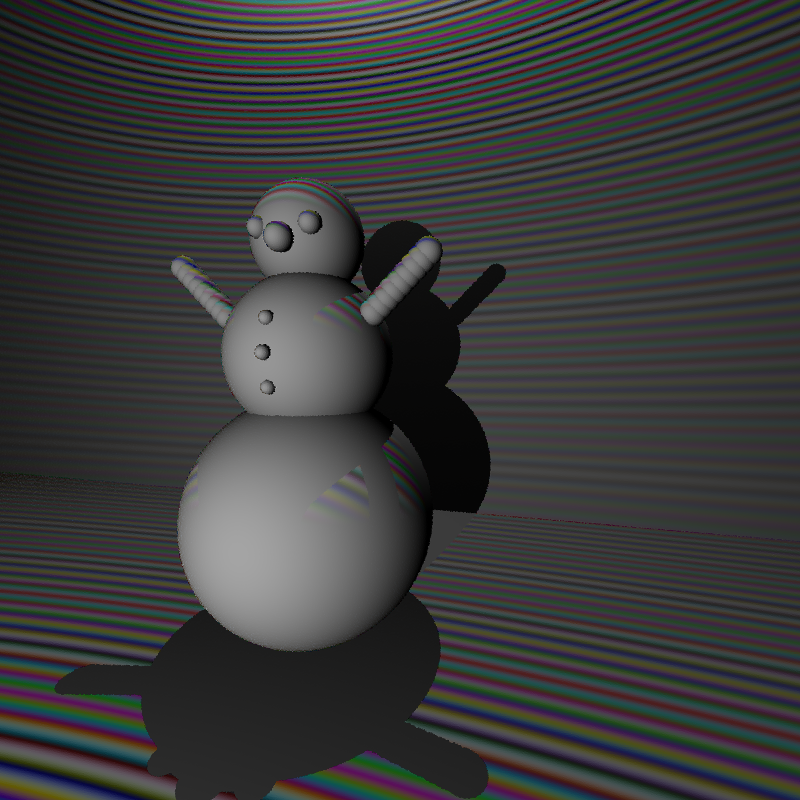
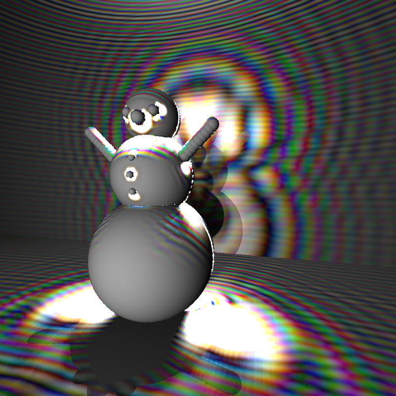
The changes to the rendering system allow for any scene comprised of spheres and triangle meshes to be rendered with diffraction and interference. Other quadric shapes, such as cylinders and cones, can be easily implemented by computing there edge bounds. A simple test scene is shown in figure 5. Here, the entire model is comprised of spheres. Comparing figure 6(c) to figure 6(b), the effect of diffraction can easily be seen.
|
|
|
(a) Without diffraction |
(b) With diffraction. The model geometry is biased towards the head, which leads to an unequal diffraction appearance. |
|
Figure 5: Diffraction from a triangle mesh. The approach will work with any polygon model.
|
|
|
||
Without interference or diffraction |
Only interference |
With diffraction |
||
Figure 6: Using only spheres, the spacing of the light sources is uniform.
Since the edge bounds are computed per face for triangle mesh objects, the distribution of the mesh geometry is important. The diffraction model assumes that the geometry distribution will be of uniform detail, so that when light sources are placed on the edges, the overall distribution will be uniform. The use of models in which the geometry is not near-uniformly distributed will cause anomalous diffraction effects. This effect can be seen on the head region of the killeroos in figure 5(b). The head appear to have much more diffracted light then the rest of the model due to the increased detail in the polygonal model in this area.
The extra prepossessing work is insignificant due to the overhead created by adding numerous light source on each edge. For the images rendered in figure 5, three light sources were added per edge, totaling approximately 5000 light sources in the scene. The rendering time for the image with and without diffraction was 6510 seconds and 34 seconds, respectively. Although this seems a detrimental slowdown, it should be noted that the image in figure 3, took well over two days to render on comparable hardware. This shows the clear downside to volume integration. The approach we have taken maintains a good balance between accuracy and rending time, with a user defined variable in the pbrt available to bias towards one of the other in the form of the number of lights to be placed per edge. Rendering time increases in the number of lights in the scene.
Conclusion
Most ray tracers work well for macroscopic objects, but when trying to render microscopic phenomena they fall short. Interference is not a large change for most ray tracers but adding diffraction seems to be a paradigm shift. Huygens'-Fresnel principle will yield diffraction for general scenes but is computationally infeasible. Geometric diffraction solves the main computational task by only requiring extra computation at the edges of object. We place light sources at the edge of objects instead of bending existing light, in order to accommodate the usual framework that ray tracers are built on. The system is flexible, working for arbitrary geometry and aviods the high costs associated with volume rendering.
Acknowledgments
A large thanks to Prof. Essam Marouf for taking time to help us through the details of Geometric Diffraction Theory, and for pointing us to invaluable resources. Thanks also to Fraser Thomson for test data, and to William Schlotter for evaluating our experiments, and proposing new ones.
Bibliography
1 Edward R. Freniere, G. Groot Gregory, and Richard A. Hassler.
- Edge diffraction in monte carlo ray tracing. Proceedings of SPIE, 1999.
2 J. Goodman.
- Introduction to Fourier Optics.
McGraw-Hill, 2nd edition edition, 1996.
3 Eugene Hecht.
- Optics. Addison-Wesley, 3rd edition, 1998.
4 Matt Pharr and Greg Humphreys.
- Pysically Based Rendering. Elsevier Inc., 2004.
5 Len Tyler.
- EE354: Introduction to scattering, course reader, Winter, 2001.
6 M. Young.
- Optics and Lasers. Springer, 5th edition edition, 2000.
Work Breakdown
Paul and Doug did almost all of the work together and saw way too much of each other. Doug did a tad bit more research, and Paul did a tad bit more programming. Most of it was pure teamwork. I dont think either of it would have understood it individually.
