Differences between revisions 6 and 7
| Deletions are marked like this. | Additions are marked like this. |
| Line 20: | Line 20: |
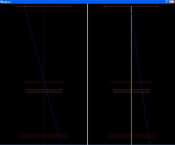
| I've also coded up a ray visualization during my hours of frustration. It wasn't very helpful because of the nature of my bugs/stupidity :-? I wrote it using OpenGL, slightly modifying some test code I wrote for some other project. |
I've also coded up a ray visualization during my hours of frustration. It wasn't very helpful because of the nature of my bugs/stupidity :-? I wrote it using OpenGL, modifying some test code I wrote for some other project. [[BR]] |
| Line 22: | Line 23: |
|
{i} [attachment:rayLG.jpg CLICK HERE TO ENLARGE] |
Assignment 3 Camera Simulation
Hyun Gu Lee
Date submitted: ?? May 2006
Code emailed: ?? May 2006
Compound Lens Simulator
Description of implementation approach and comments
It is said that one does not feel the passage of time when one engages in an activity that is enjoyable. I, for some reason, did not feel the passage of time while working on this assignment ![]() . While I won't go into every little mistake that has kept me from finishing this, I will give a broad overview of what I did.
. While I won't go into every little mistake that has kept me from finishing this, I will give a broad overview of what I did.
First, off in the camera constructor, I build and store the data structure for the lens surfaces. I also calculate useful variables here such as total thickness of all lenses, length of each side of the film, and Area of back lens over film distance squared.
In GenerateRay, I find convert the given imageX and imageY coordinates from raster to camera coordinates. After calling ConcentricSampleDisk, I compute the camera coordinates of the sampled point on the back lens. By using these two points, I get the initial ray direction and origin. It is "important" to remember to normalize this initial ray direction if vector form of Snell's law is used later on.
The ray then goes through each lens surface. If the current surface is actually a aperture stop, a ray-plane intersection is performed. The distance from the intersection point to the z-axis is computed. If this is larger than the given aperture, this ray is blocked, so we return. For other lens surfaces, the intersection is computed using ray-sphere intersection. This code is heavily borrowed from pbrt. After the intersection point is computed, its distance from the z-axis is compared to the aperture. Again, if the ray is outside the aperture of the lens, we return. Now, we compute the new ray direction using the vector form of Snell's law. (Much easier to use!). We check for internal reflection, then continue with the loop.
After we're done going through all the lens surfaces, the ray is converted to World coordinates. We do some housekeeping with various ray members, then compute the weight for irradiance calculation.
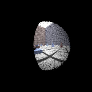
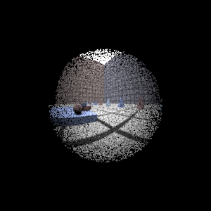
I've also coded up a ray visualization during my hours of frustration. It wasn't very helpful because of the nature of my bugs/stupidity ![]() I wrote it using OpenGL, modifying some test code I wrote for some other project.
I wrote it using OpenGL, modifying some test code I wrote for some other project.
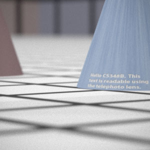
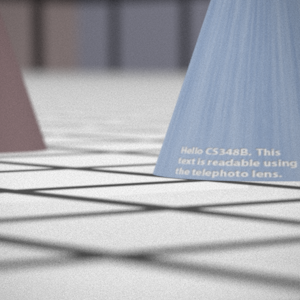
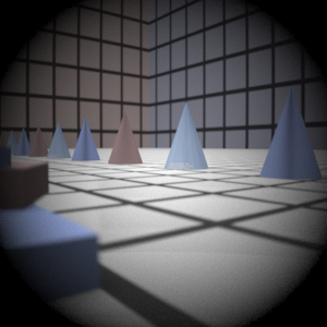
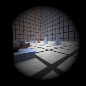
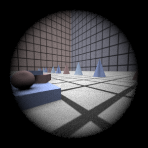
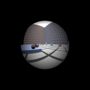
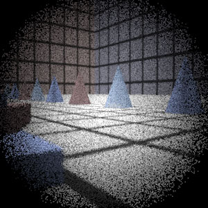
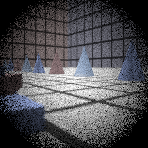
Final Images Rendered with 512 samples per pixel
|
My Implementation |
Reference |
Telephoto |
|
|
Double Gausss |
|
|
Wide Angle |
|
|
Fisheye |
|
|
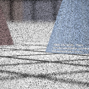
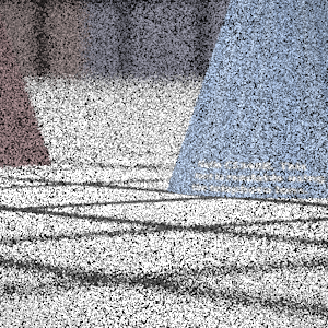
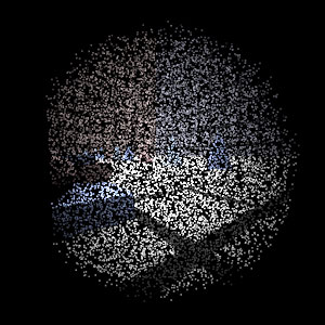
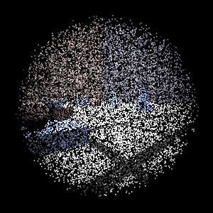
Final Images Rendered with 4 samples per pixel
|
My Implementation |
Reference |
Telephoto |
|
|
Double Gausss |
|
|
Wide Angle |
|
|
Fisheye |
|
|
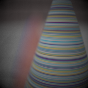
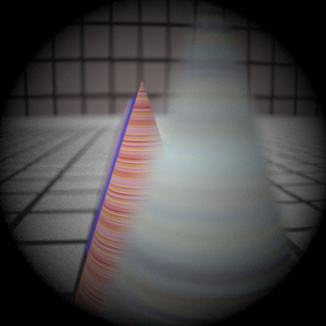
Experiment with Exposure
Image with aperture full open |
Image with half radius aperture |
|
|
Observation and Explanation
......
Autofocus Simulation
Description of implementation approach and comments
......
Final Images Rendered with 512 samples per pixel
|
Adjusted film distance |
My Implementation |
Reference |
Double Gausss 1 |
mm |
|
|
Double Gausss 2 |
mm |
|
|
Telephoto |
mm |
|
|
Any Extras
...... Go ahead and drop in any other cool images you created here .....
