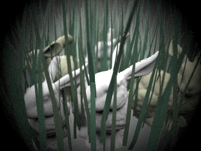
Assignment 3 Camera Simulation
Murad Akhter
Date submitted: 12th May 2006
Code emailed: 12th May 2006
Compound Lens Simulator
Description of implementation approach and comments
1. Lens system
I began the assignment by implementing a datastructure to store the lens parameters. I treated the aperture stop and all the lens elements the same way and used the same LensElement class for them. The lens as a whole was just a vector of these objects. I adapted the code for reading in auto focus zones in order to read in the lens input .dat files. As I stored the various parameters in each LensElement, I also stored the right and left refractive index, setting the value to 1 for the aperture stop. Each LensElement also had a reference to a PBRT shape for ray / lens element intersection tests. I used a disk for the aperture stop and a partial sphere for the rest, calculating the zmin and zmax values from the relative position of each lens element as I initialized them and their respective apertures. I just had to use some basic algebra and a few trig functions to compute these values. For convex lenses I set the center z position of the sphere towards the image and vice versa for concave lenses. Similarly I reversed the sphere orientation for concave lenses. This setup allowed me to trace rays through the lens system in any direction I wanted. I could iterating through the vector in ascending or descending order and flip the surface normals for Snell's law when appropriate. The directions were initialized for traversal from image to object space and flipped when traversing in the opposite direction. Being able to trace rays in both directions came in handy when I computed the thick lens approximation for my autofocus algorithm.
2. Tracing rays
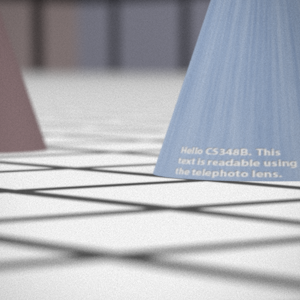
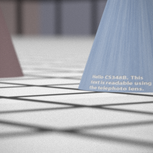
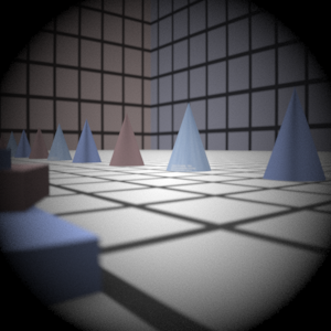
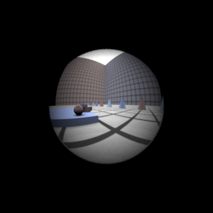
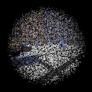
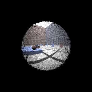
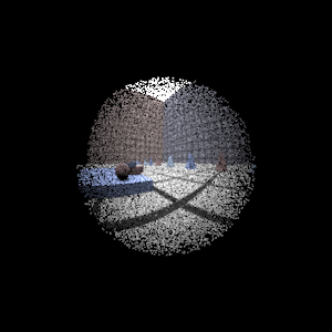
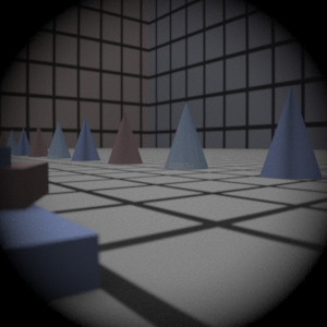
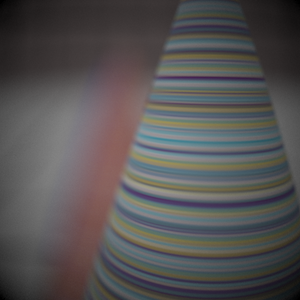
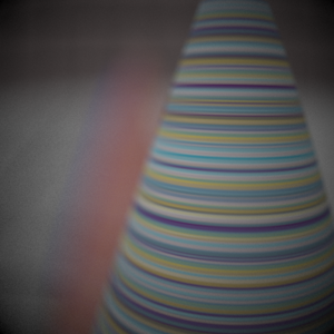
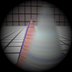
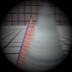
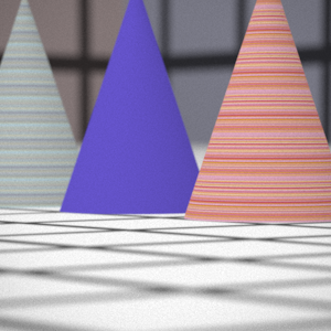
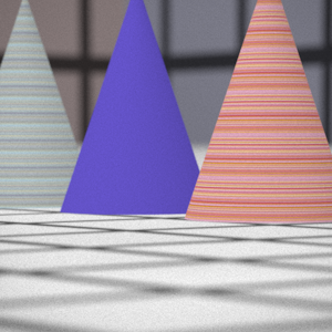
For this part I just set up each sample ray as recommended in the handout and then traced its path through the lens system using Snell's law to refract the rays. To converte image coordinates to camera coordinates I used the ratio between the film diagonal and the raster diagonal along with the horizontal and vertical resolution to compute the screen extent. I combined this with the lens thickness plus film distance translation to the film plane to compute and store a RasterToCamera transform that I could then use for each sample point. So after picking a point on the raster and converting to camera coordinates, I used it to set the ray origin. To set the ray direction, I subtracted the origin from the uniform sample values computed by ConcentricSampleDisk() after they were scaled by the radius of the back lens. The direction was normalized so that I could use the vector form of Snell's law by Hanrahan' 84. Each ray that successfully made it through the lens system was weighted by cos(theta)4 * A/d2 where theta was the angle the ray made with the film normal (and cos theta was just their dot product), A was the area of the back lens and d the distance to the film plane. Rays that didn't make it were given a weight of 0. This caused a nasty bug on my Mac, however, since it ended up setting alpha to zero for some pixels in the images. This is because the Scene::Render function doesn't normally initalize alpha and won't set it if the ray weight is zero. I fixed this by initializing the value to 1 in my scene.cpp file. I assume this problem isn't apparent on Linux and XP.
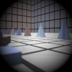
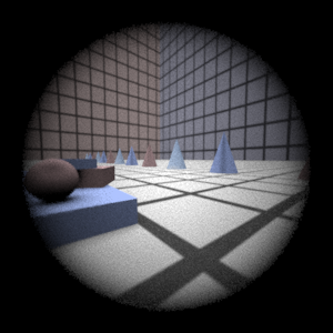
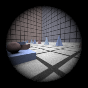
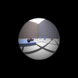
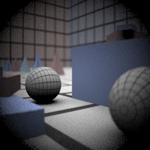
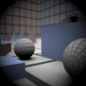
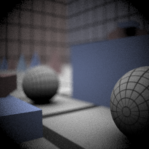
Final Images Rendered with 512 samples per pixel
|
My Implementation |
Reference |
Telephoto |
|
|
Double Gausss |
|
|
Wide Angle |
|
|
Fisheye |
|
|
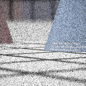
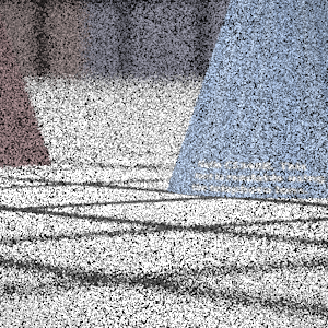
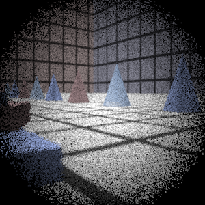
Final Images Rendered with 4 samples per pixel
|
My Implementation |
Reference |
Telephoto |
|
|
Double Gausss |
|
|
Wide Angle |
|
|
Fisheye |
|
|
Experiment with Exposure
Image with aperture full open |
Image with half radius aperture |
|
|
Observation and Explanation
As is easy to see, the image on the right is dimmer once the aperture size is reduced. The exposure of the image depends on the number of rays that can pass through the lens system unobstructed. Reducing the aperture size by half reduces the area rays can pass through by a quarter. This equals 2 f-stops since one stop corressponds to halving of the light intensity from the previous stop. Reducing the aperture should also increase the depth of field but I can't tell by looking at the two images.
Autofocus Simulation
Description of implementation approach and comments
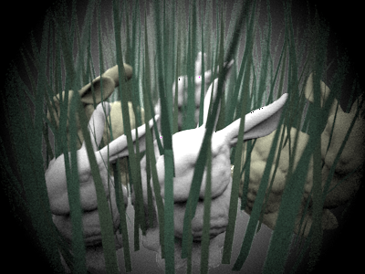
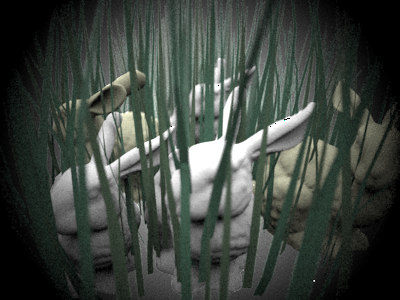
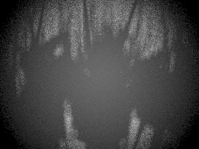
For my autofocus implementation I simply use depth information stored in the maxt ray variable as a result of ray-object intersections. My autofocus algorithm transforms the ray to camera coordinates and figures out the z value at the point of intersection for each ray (by simply using the maxt values stored in each ray after a successfull intersection). These z values are stored and sorted for each autofocus region and then analyzed to detect the z value for foreground objects. I do this by detecting sharp changes in the z values and comparing them against an incremental average by scanning values from closest to furthest. If I don't detect any sharp changes I simply select the median z value since it's the best focus estimate for that range. Otherwise I use the incremental average. Here's an example image of the bunny scene showing the change in depth values:
For multiple autofocus regions I simply compute the average z value. I also have a "af_mode" setting that can be set to "foreground" or "background" to select the closest or furthest distance to focus on. I've posted example images below showing the effects of the settings. Note that once I have computed the z I want to focus on, I simply use the thick lens approximation to set the film distance. This only involves computing the focal length by tracing rays from object to image space and the intersection points p', f', p and f as described in the Kolb paper. These values can then be used in the equation given in the paper that 1/z' - 1/z = 1/f' to get the film distance.
Final Images Rendered with 512 samples per pixel
|
Adjusted film distance |
My Implementation |
Reference |
Double Gausss 1 |
61.5 mm |
|
|
Double Gausss 2 |
38.4 mm |
|
|
Telephoto |
117.5 mm |
|
|
Extras
Stopping Down the Telephoto Lens
Image with aperture full open |
Image with quarter diameter aperture |
Exposure increased by 4-stops in Photoshop |
|
|
|
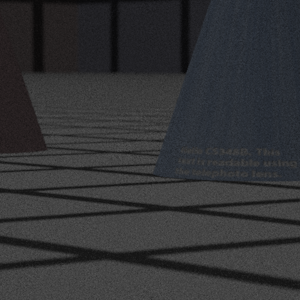
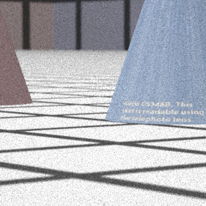
I reduced the aperture to 1/4 th its original value to observe a 4-stop change in exposure. Increasing the exposure in Photoshop gave an image that seemed similar to the original. The reduced aperture size causes the images to be noisier since fewer rays end up making it to the scene from the camera. This is easy to see when comparing the Photoshop image with the original image on the leftmost column.
More Complex Auto Focus
Background |
Normal |
Foreground |
|
|
|
Here are results from a similar experiment with the bunnies scene. It's easier to see the difference when the foreground and background focused images are next to each other. Unfortunately as the bunnies ar closely packed, even this comparision isn't very obvious unless you pay attention to the foreground bushes or the distant bunny in the center of the image.
Background |
Foreground |
|
|
Here's the normal image that is generated if neither mode is selected
