Foam
By Sean Rosenbaum and Mattias Bergbom
‘‘We live in a universe inundated with foam.’’ - S. Perkowitz
Goal
We intended to render dense foam formations in a physically-correct way. To our knowledge this has never been done (physically-correct). Foam plays such a large role in the appearance of fluids that it is a shame for it not to be taken seriously. We strived to lay some foundation for others to build on.
Related Work
Foam plays a significant part in many petrochemical, biophysical and structural engineering processes, and as such has attracted huge interest from many research fields. For instance, Phelan et al. (1995) and Kraynik et al. (2003) both use CGAL-based Surface Evolver to compute various geometrical and structural properties in monodisperse foam. However, little work has been done in visualizing dense foams in a convincing manner. We draw most of our information from the work of Kück et al. (2002), who simulate and visualize semi-dense foam using an approximate bubble intersection technique, and Glassner (2000), who created double- and triple-bubble formations with physically correct interfaces using CG scripting.
Foundation
When we first got started, we knew the bubble intersection geometry and thin-film interference were crucial, regardless of our final solution, so we began working on them immediately. They form the foundation of the brute-force physical model.
Geometry
Foam is essentially a collection of gas bubbles enclosed in liquid. The gas-liquid ratio varies, but gas generally dominates in the order of 10 to 1 or more. Each bubble-bubble intersection is a thin wall through which liquid constantly travels under the influence of gravity. Where such walls meet triangular tubes form - called Plateau borders - through which even more liquid is advected.
The bubbles are an equilibrium between internal gas pressure and external surface tension. When bubbles interact, there is an intricate balancing act between the repulsive force due to the interest of maintaining a perfectly spherical (and thus minimal) surface, and the attractive force caused by the opportunity to share the separating film and decrease the overall surface area.
Foam is thus generally extremely unstable, and constantly evolves through the advection of liquid and the forming and dissoluion of bubbles.
Glassner (2001) uses Plateau's results to derive the optimal distances between pairs and triplets of bubbles, expressed in their respective radii.
Relaxation...
Thin-film interference
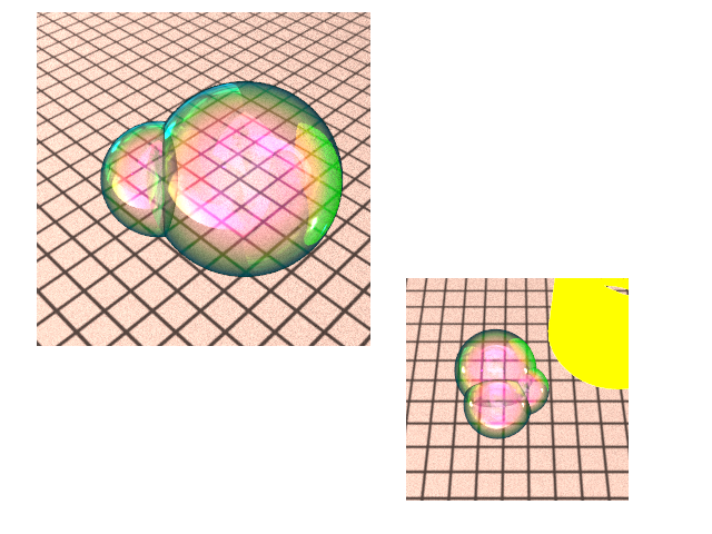
When light hits the surface of a bubble, there is immediately some reflection, as well as some transmission into the film. The transmitted light hit the inner end of the film where it may reflect again and then once more along the outer boundary, leaving it with the same direction as the initial reflection even after accounting for refraction. The light will undergo some phase change, which when combined with the reflection, gives us an interference pattern. Technically there may be many bounces within the film, though we decided to only model the first bounce back as others have done. The main difficulty in implementing thin-film interference is actually extending PBRT to use wavelength in place of the given spectrum representation. Initially we have an RGB 3-tuple for the light that we convert to wavelength using the Fourier-basis conversion described by Glassner []. We then compute the interference color using the equations presented by [], and convert the wavelength back to XYZ and then to RGB. Who does not love color conversion?
The image below demonstrates the geometry and interference.
Limitations
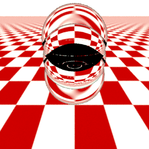
Originally we were really excited about tracing rays through the geometric model to develop a pure BSSRDF of the foam (more on that in our conclusions). To our dismay, we realized we were not going to pull it off. The image below is worth a thousand heads slammed against a desk.
Obviously tracing rays through bubble formations is intractable. Each time a ray hits the surface of a bubble, we get two rays, one for the reflection and another for transmission. Even just tracing sparse formations in a reasonable amount of time proved troublesome.
Shell Scattering
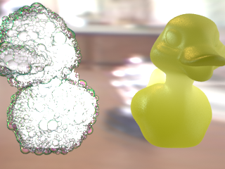
We propose a technique we call "shell scattering" which overcomes the recursion limit by only tracing through several layers of geometry, then falling back on a simpler subsurface scattering approximation as we penetrate deeper. This technique enables us to capture the bulk of the optical properties and complexity in a reasonable amount of time.
To achieve this, we had to augment our system with a BSSRDF. We chose to implement Jensen's hierarchical subsurface scattering algorithm [] because of its speed and effectiveness. This algorithm has been implemented a number of times in the past few years by other students, so we will refer the reader to both the paper and the other entries for spurious details. The idea is simply to compute the irradiance at a number of sample points over the mesh with photon mapping or irradiance caching. Then a hierarchical structure is built for efficiently computing the contributions from surrounding area for the radiance at a given point. The structure is simply traversed in the manner described by Jensen, with an approximation being used when the error is small. Jensen suggests Turk's method be used for sampling the points on the mesh. We found that in practice the vertices, weighted by area, work well as long as the mesh is adequately complex. This was not at all a problem for us since our meshes are fairly smooth and hence adequately sampled. We suspect that in most cases people can get away with this.
We also extended our bubble formations to work on arbitrary meshes. Below we demonstrate the shell method, along with our subsurface scattering in isolation.
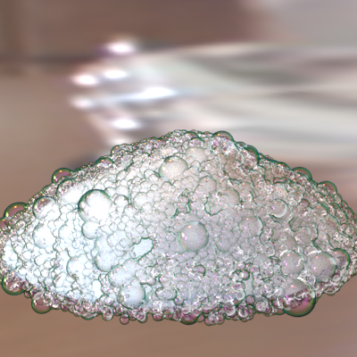
Here we demonstrate this on a foam-like mesh.
Conclusion
While we believe we made good progress, it is clear there is more to be done. Sure, one can hack together something that looks like foam using some procedural textures and bump or displacement mapping, but doing it in a physically-correct way is another story, one that we hope you can now appreciate. Our technique dealt with the intractability of the problem in an approximately physically-correct way. In particular, it renders large dense foam formations in high resolution in only a few hours on one of the myth machines, rather than several days on a state-of-the-art 300 machine cluster tracing through all the geometry. Our method fully scatters light, demonstrates geometric complexity and optics, and is relatively fast.
Limitations include its.... and sampling problems... The BSSRDF is also incorrect. As we said above, we did not have the resources to trace through dense foam to experimentally derive the scattering and absorption terms. We had no choice but to guesstimate them.
It would also be interesting applying the same idea to other homogeneous translucent bodies. That is, physically modeling several layers of the surface, then eventually falling back to a BSSRDF as our rays penetrate deeper.
Extras: Scene Fudge
We procedurally generated our own biologically-motivated leaf venation patterns. The leaf starts out small, with some point to begin vein growth. We then iteratively grow the veins and the leaf based on the chosen growth model. At each iteration, we expand each vein along the center of mass of nearby auxin-sources. As the veins lengthen, they become fatter. We have implemented uniform and marginal growth. In uniform growth, auxin sources are equally likely to be spawned anywhere in the interior of the leaf at each iteration. On the other hand, marginal growth spawns auxin only along the boundary as the leaf is grown. This is based on algorithms described in []. After these veins are produced, we overlay the texture with a Worley noise [] we wrote to take the place of the more complicated tertiary veins exhibited by some plants. We use a grid to accelerate both of these processes. [] actually introduced an algorithm to account for the latter sort of veins, but it is very ineffecient without more complicated acceleration algorithms. We felt Worley textures were good enough for us and would save us some time.
We demonstrated a nice visualization of this, which unfortunately many people had trouble seeing during the demonstration. It produced the texture below. We encourage you to view it here.
Here it's used as a bump-map in a scene rendered in Blender.
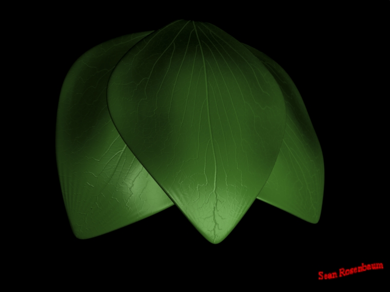
We initially intended to use these textures as bump-maps, but we had trouble getting the texture coordinates of our leaf models loaded properly in PBRT, so we ended up using the texture as a displacement map in 3D Studio, then exporting the geometry. The final scene we demoed did a rather bad job of demonstrating these textures because there is a lot of light all over the scene and the resolution was not very high. We probably also should have used more displacement to exaggerate them a little. The leaf model was rendered with a mix of our BSSRDF to account for internal scattering and a lambertian BRDF for the roughness of the surface of leaves. We found this "hack" enabled us to get some interesting translucency while having a rough surface. It also has the advantage of working well if you want to apply bump maps when Jensen's hierarchical algorithm is used.
We also spent a few days dabbling with fluid-simulation. Specifically, we extended the 2D fluid simulator described in [] to 3D with arbitrary boundaries. In order to add arbitrary 3D boundaries, we had to voxelize the world. We specify some point in the scene that identifies which volume should be filled to distinguish between the visible world and the inside of a mesh. We then came up with a flood-fill like algorithm that radiates out from the grid at the chosen point determining whether or not it is a boundary by shooting a ray in that grid's direction to check for intersection with objects in the scene. Otherwise, extending the simulation to 2D was straightforward for the most part.
[Voxelized World]
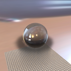
Magic Sphere. Demonstrates boundary awareness
To make steam, we spawned density along the surface of the volume and added some buoyancy force there. We also included a general force to uniformly push the fluid in the volume to account for gravity, wind, and so on. We then go through several iterations, continually adding density along the surface as it dissipates to physically simulate the effect.
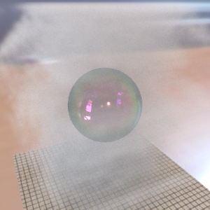
Steamy Bubble. The artifacts at the edges result from making the volume smaller than the scene in view.
Final Scene
Lessons Learned
1) Technology is only one factor
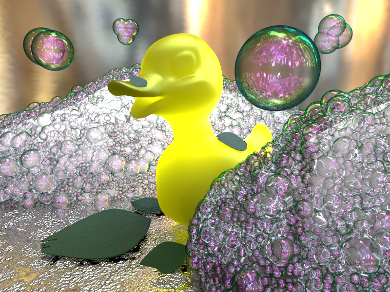
We spent an enormous amount of time developing all the technology for rendering foam and some other things in the scene. Consequently, we did not have much time to put things together in the final image, though we did manage to quickly put together something we were happy with. We ended up starting the render at the last minute and had to exclude the steam because it slows the rendering down tremendously. We also did not realize the leaf patterns were not showing up well until a few hours prior to the demo and proceeded regardless. The lighting, as well, was problematic. Environmental lighting often washes out translucent material and makes it look more uniform when the lighting does not vary that significantly. Our final image suffered as a result of these issues.
2) Experimentation is costly
Since this problem was largely unexplored, we had to develop our own solution. As stated above, we experimented a great deal - and experimentation of course is a major time sink. And again, we sought to do things physically-correct, which we found made things extremely difficult. To be honest, may have been able to produce a prettier image with a lot less effort using some noise functions for rendering very dense formations, though as we said, this sort of thing was not our goal. This made producing a pretty picture immensely more challenging for us, though we feel it looks impressive nonetheless!
References
Andrew Glassner. "How to derive a spectrum from an RGB triplet". IEEE 1989.
Andrew Glassner. "Soap Bubbles: Part 2". IEEE 2000.
Henrik Wann Jensen and Juan Buhler. "A rapid hierarchical rendering technique for translucent materials". SIGGRAPH 2002.
Henrik Wann Jensen, Stephen R. Marschner, Marc Levoy, and Pat Hanrahan. "A Practical model for subsurface light transport". SIGGRAPH 2001.
Adam Runions, Martin Fuhrer, Brendan Lane, Pavol Federl, Anne-Gaëlle Rolland-Lagan and Przemyslaw Prusinkiewicz. "Modeling and visualization of leaf venation patterns". SIGGRAPH 2005
Steven Worley. "A cellular texture basis function". SIGGRAPH 1996.
Jos Stam. "Real-Time Fluid Dynamics for Games". Game Developer Conference 2003.
Jos Stam. "Stable Fluids". SIGGRAPH 1999.
Division of Labor
We split the project into two parts: general rendering and bubble geometry, formation, and intersection. This allowed each of us to specialize in a particular area, rather than force each of us to be a jack of all trades. However, we were in constant communication and worked out the general direction of the project together.
Sean Rosenbaum
Thin-Film Interference
Hierarchical Subsurface Scattering
Venation Patterns
Steam Simulator
Mattias Bergbom
Bubble Geometry and Intersection
Foam Relaxation
Bubble Sampling Meshes