Click slide for next, or goto previous, first, last slides or back to thumbnail layout.
Click slide for next, or goto previous, or back to thumbnail layout.
Click slide for next, or goto previous, first, last slides or back to thumbnail layout.
Click slide for next, or goto previous, or back to thumbnail layout.
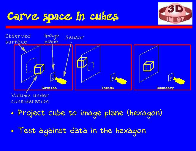
These three images illustrate how we carve space a cube at a time. In each picture we have a range sensor that is looking at a planar surface. The small rectangle in front of the sensor denotes the sensor's image plane. The cube denotes a volume that we are examining.
In the first image the cube is in front of the observed surface, so it must be in empty space, and therefore it can be discarded. In the second image the cube is behind the observed surface, so it is inside the object as far as this view is concerned. In the third image the cube intersects the observed data and is labeled to be on the object boundary.
Classification of a cube is relatively straightforward. First, we project the eight corners of a cube to the image plane, where their convex hull typically forms a hexagon. We only need to check the points within the hexagon whether they all are in front of or behind the cube, or whether the cube is in the middle of the data. Note that if we can label parts of the range maps to be background, we can discard cubes that project there without looking at the actual range values. In a controlled scanning environment obtaining the labeling is not very difficult. Let's assume that the scene and scanner are stationary between scans, but the object is repositioned for each scan. One could, for example, first scan the empty scene. Data points in later scans that match the corresponding points in the first scan can be labeled background.