Our algorithm employs a continuous implicit function, ![]() ,
represented by samples. The function we represent is the weighted
signed distance of each point
,
represented by samples. The function we represent is the weighted
signed distance of each point ![]() to the nearest range surface
along the line of sight to the sensor. We construct this function by
combining signed distance functions
to the nearest range surface
along the line of sight to the sensor. We construct this function by
combining signed distance functions ![]() ,
, ![]() ,
...
,
... ![]() and weight functions
and weight functions ![]() ,
, ![]() , ...
, ... ![]() obtained from range images 1 ... n. Our
combining rules give us for each voxel a cumulative signed distance
function,
obtained from range images 1 ... n. Our
combining rules give us for each voxel a cumulative signed distance
function, ![]() , and a cumulative weight
, and a cumulative weight ![]() . We
represent these functions on a discrete voxel grid and extract an
isosurface corresponding to
. We
represent these functions on a discrete voxel grid and extract an
isosurface corresponding to ![]() . Under a certain set of
assumptions, this isosurface is optimal in the least squares sense. A
full proof of this optimality is beyond the scope of this paper, but a
sketch appears in appendix A.
. Under a certain set of
assumptions, this isosurface is optimal in the least squares sense. A
full proof of this optimality is beyond the scope of this paper, but a
sketch appears in appendix A.
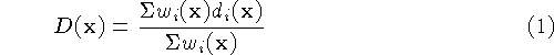
Figure 2 illustrates the principle of combining unweighted signed distances for the simple case of two range surfaces sampled from the same direction. Note that the resulting isosurface would be the surface created by averaging the two range surfaces along the sensor's lines of sight. In general, however, weights are necessary to represent variations in certainty across the range surfaces. The choice of weights should be specific to the range scanning technology. For optical triangulation scanners, for example, Soucy [25] and Turk [30] make the weight depend on the dot product between each vertex normal and the viewing direction, reflecting greater uncertainty when the illumination is at grazing angles to the surface. Turk also argues that the range data at the boundaries of the mesh typically have greater uncertainty, requiring more down-weighting. We adopt these same weighting schemes for our optical triangulation range data.
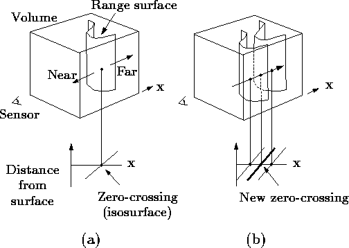
Figure 2: Unweighted signed distance
functions in 3D. (a) A range sensor looking down the x-axis observes
a range image, shown here as a reconstructed range surface. Following
one line of sight down the x-axis, we can generate a signed distance
function as shown. The zero crossing of this function is a point on
the range surface. (b) The range sensor repeats the measurement, but
noise in the range sensing process results in a slightly different
range surface. In general, the second surface would interpenetrate
the first, but we have shown it as an offset from the first surface
for purposes of illustration. Following the same line of sight as
before, we obtain another signed distance function. By summing these
functions, we arrive at a cumulative function with a new zero crossing
positioned midway between the original range measurements.
Figure 3 illustrates the construction and usage of
the signed distance and weight functions in 1D. In
Figure 3a, the sensor is positioned at the origin
looking down the +x axis and has taken two measurements, ![]() and
and
![]() . The signed distance profiles,
. The signed distance profiles, ![]() and
and ![]() may extend
indefinitely in either direction, but the weight functions,
may extend
indefinitely in either direction, but the weight functions, ![]() and
and ![]() , taper off behind the range points for reasons discussed
below.
, taper off behind the range points for reasons discussed
below.
Figure 3b is the weighted combination of the two profiles. The combination rules are straightforward:
where, ![]() and
and ![]() are the signed distance and
weight functions from the ith range image.
are the signed distance and
weight functions from the ith range image.
Expressed as an incremental calculation, the rules are:
where ![]() and
and ![]() are the cumulative signed
distance and weight functions after integrating the ith range
image.
are the cumulative signed
distance and weight functions after integrating the ith range
image.
In the special case of one dimension, the zero-crossing of the cumulative function is at a range, R given by:
![]()
i.e., a weighted combination of the acquired range values, which is what one would expect for a least squares minimization.
Figure 3: Signed
distance and weight functions in one dimension. (a) The
sensor looks down the x-axis and takes two measurements, ![]() and
and
![]() .
. ![]() and
and ![]() are the signed distance profiles, and
are the signed distance profiles, and
![]() and
and ![]() are the weight functions. In 1D, we might
expect two sensor measurements to have the same weight magnitudes, but
we have shown them to be of different magnitude here to illustrate how
the profiles combine in the general case. (b) D(x) is a
weighted combination of
are the weight functions. In 1D, we might
expect two sensor measurements to have the same weight magnitudes, but
we have shown them to be of different magnitude here to illustrate how
the profiles combine in the general case. (b) D(x) is a
weighted combination of ![]() and
and ![]() , and W(x) is the sum
of the weight functions. Given this formulation, the zero-crossing,
R, becomes the weighted combination of
, and W(x) is the sum
of the weight functions. Given this formulation, the zero-crossing,
R, becomes the weighted combination of ![]() and
and ![]() and
represents our best guess of the location of the surface. In
practice, we truncate the distance ramps and weights to the vicinity
of the range points.
and
represents our best guess of the location of the surface. In
practice, we truncate the distance ramps and weights to the vicinity
of the range points.
In principle, the distance and weighting functions should extend indefinitely in either direction. However, to prevent surfaces on opposite sides of the object from interfering with each other, we force the weighting function to taper off behind the surface. There is a trade-off involved in choosing where the weight function tapers off. It should persist far enough behind the surface to ensure that all distance ramps will contribute in the vicinity of the final zero crossing, but, it should also be as narrow as possible to avoid influencing surfaces on the other side. To meet these requirements, we force the weights to fall off at a distance equal to half the maximum uncertainty interval of the range measurements. Similarly, the signed distance and weight functions need not extend far in front of the surface. Restricting the functions to the vicinity of the surface yields a more compact representation and reduces the computational expense of updating the volume.
In two and three dimensions, the range measurements correspond to curves or surfaces with weight functions, and the signed distance ramps have directions that are consistent with the primary directions of sensor uncertainty. The uncertainties that apply to range image integration include errors in alignment between meshes as well as errors inherent in the scanning technology. A number of algorithms for aligning sets of range images have been explored and shown to yield excellent results [11][30]. The remaining error lies in the scanner itself. For optical triangulation scanners, for example, this error has been shown to be ellipsoidal about the range points, with the major axis of the ellipse aligned with the lines of sight of the laser [13][24].
Figure 4 illustrates the two-dimensional case for
a range curve derived from a single scan containing a row of range
samples. In practice, we use a fixed point representation for the
signed distance function, which bounds the values to lie between
![]() and
and ![]() as shown in the figure. The values of
as shown in the figure. The values of
![]() and
and ![]() must be negative and positive, respectively,
as they are on opposite sides of a signed distance zero-crossing.
must be negative and positive, respectively,
as they are on opposite sides of a signed distance zero-crossing.
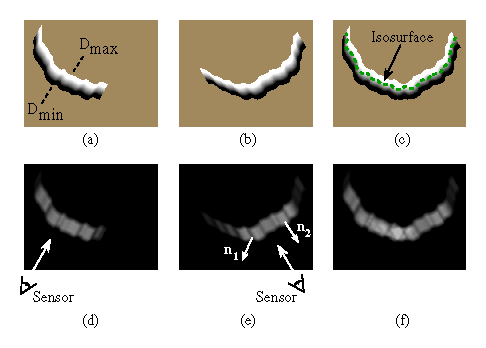
Figure 4: Combination of signed distance and weight functions in two
dimensions. (a) and (d) are the signed distance and weight functions,
respectively, generated for a range image viewed from the sensor line
of sight shown in (d). The signed distance functions are chosen to
vary between ![]() and
and ![]() , as shown in (a). The weighting
falls off with increasing obliquity to the sensor and at the edges of
the meshes as indicated by the darker regions in (e). The normals,
, as shown in (a). The weighting
falls off with increasing obliquity to the sensor and at the edges of
the meshes as indicated by the darker regions in (e). The normals,
![]() and
and ![]() shown in (e), are oriented at a grazing
angle and facing the sensor, respectively. Note how the weighting is
lower (darker) for the grazing normal. (b) and (e) are the signed
distance and weight functions for a range image of the same object
taken at a 60 degree rotation. (c) is the signed distance function
shown in (e), are oriented at a grazing
angle and facing the sensor, respectively. Note how the weighting is
lower (darker) for the grazing normal. (b) and (e) are the signed
distance and weight functions for a range image of the same object
taken at a 60 degree rotation. (c) is the signed distance function
![]() corresponding to the per voxel weighted combination of
(a) and (b) constructed using equations 3 and 4. (f) is the sum of
the weights at each voxel,
corresponding to the per voxel weighted combination of
(a) and (b) constructed using equations 3 and 4. (f) is the sum of
the weights at each voxel, ![]() . The dotted green curve in
(c) is the isosurface that represents our current estimate of the
shape of the object.
. The dotted green curve in
(c) is the isosurface that represents our current estimate of the
shape of the object.
For three dimensions, we can summarize the whole algorithm as follows. First, we set all voxel weights to zero, so that new data will overwrite the initial grid values. Next, we tessellate each range image by constructing triangles from nearest neighbors on the sampled lattice. We avoid tessellating over step discontinuities (cliffs in the range map) by discarding triangles with edge lengths that exceed a threshold. We must also compute a weight at each vertex as described above.
Once a range image has been converted to a triangle mesh with a weight at each vertex, we can update the voxel grid. The signed distance contribution is computed by casting a ray from the sensor through each voxel near the range surface and then intersecting it with the triangle mesh, as shown in figure 5. The weight is computed by linearly interpolating the weights stored at the intersection triangle's vertices. Having determined the signed distance and weight we can apply the update formulae described in equations 3 and 4.
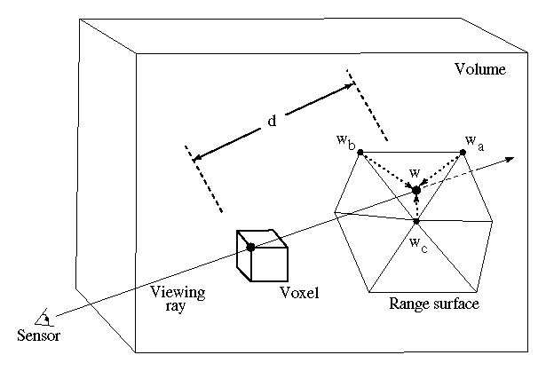
Figure 5: Sampling the range surface to update the volume. We compute the
weight, w, and signed distance, d, needed to update the voxel by
casting a ray from the sensor, through the voxel onto the range
surface. We obtain the weight, w, by linearly interpolating the
weights ( ![]() ,
, ![]() , and
, and ![]() ) stored at neighboring range
vertices. Note that for a translating sensor (like our Cyberware
scanner), the sensor point is different for each column of range
points.
) stored at neighboring range
vertices. Note that for a translating sensor (like our Cyberware
scanner), the sensor point is different for each column of range
points.
At any point during the merging of the range images, we can extract the zero-crossing isosurface from the volumetric grid. We restrict this extraction procedure to skip samples with zero weight, generating triangles only in the regions of observed data. We will relax this restriction in the next section.