We show results for a number of objects designed to explore the robustness of our algorithm, its ability to fill gaps in the reconstruction, and its attainable level of detail. To explore robustness, we scanned a thin drill bit using the traditional method of optical triangulation. Due to the false edge extensions inherent in data from triangulation scanners [6], this particular object poses a formidable challenge, yet the volumetric method behaves robustly where the zippering method [30] fails catastrophically. The dragon sequence in Figure 9 demonstrates the effectiveness of carving space for hole filling. The use of a backdrop here is particularly effective in filling the gaps in the model. Note that we do not use the backdrop at all times, in part because the range images are much denser and more expensive to process, and also because the backdrop tends to obstruct the path of the object when automatically repositioning it with our motion control platform. Finally, the ``Happy Buddha'' sequence in Figure 10 shows that our method can be used to generate very detailed, hole-free models suitable for rendering and rapid manufacturing.
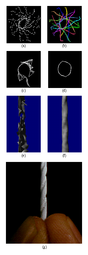
Figure 8: Merging range images of a drill bit. We scanned a 1.6 mm drill bit
from 12 orientations at a 30 degree spacing using traditional optical
triangulation methods. Illustrations (a) - (d) each show a plan (top)
view of a slice taken through the range data and two reconstructions.
(a) The range data shown as unorganized points: algorithms that
operate on this form of data would likely have difficulty deriving the
correct surface. (b) The range data shown as a set of wire frame
tessellations of the range data: the false edge extensions pose a
challenge to both polygon and volumetric methods. (c) A slice through
the reconstructed surface generated by a polygon method: the zippering
algorithm of Turk [31]. (d) A slice through the reconstructed surface
generated by the volumetric method described in this paper. (e) A
rendering of the zippered surface. (f) A rendering of the
volumetrically generated surface. Note the catastrophic failure of
the zippering algorithm. The volumetric method, however, produces a
watertight model. (g) A photograph of the original drill bit. The
drill bit was painted white for scanning.
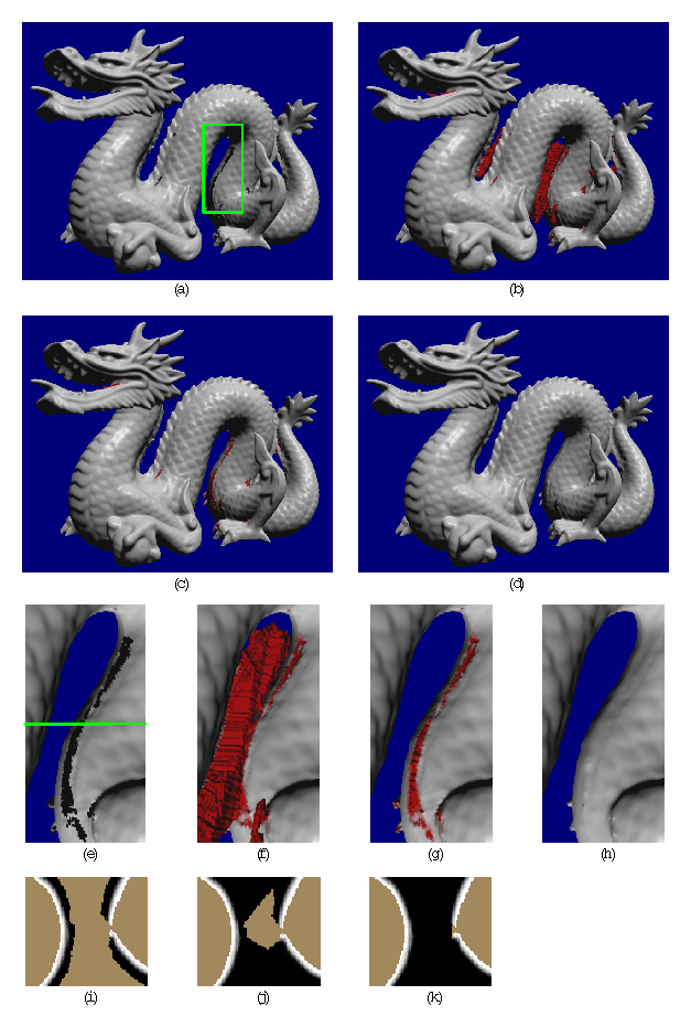
Figure 9: Reconstruction of a dragon. Illustrations (a) - (d) are full views
of the dragon. Illustrations (e) - (h) are magnified views of the
section highlighted by the green box in (a). Regions shown in red
correspond to hole fill triangles. Illustrations (i) - (k) are slices
through the corresponding volumetric grids at the level indicated by
the green line in (e). (a)(e)(i) Reconstruction from 61 range images
without space carving and hole filling. The magnified rendering
highlights the holes in the belly. The slice through the volumetric
grid shows how the signed distance ramps are maintained close to the
surface. The gap in the ramps leads to a hole in the reconstruction.
(b)(f)(j) Reconstruction with space carving and hole filling using the
same data as in (a). While some holes are filled in a reasonable
manner, some large regions of space are left untouched and create
extraneous tessellations. The slice through the volumetric grid
reveals that the isosurface between the unseen (brown) and empty
(black) regions will be connected to the isosurface extracted from the
distance ramps, making it part of the connected component of the
dragon body and leaving us with a substantial number of false
surfaces. (c)(g)(k) Reconstruction with 10 additional range images
using ``backdrop'' surfaces to effect more carving. Notice how the
extraneous hole fill triangles nearly vanish. The volumetric slice
shows how we have managed to empty out the space near the belly. The
bumpiness along the hole fill regions of the belly in (g) corresponds
to aliasing artifacts from tessellating over the discontinuous
transition between unseen and empty regions. (d)(h) Reconstruction as
in (c)(g) with filtering of the hole fill portions of the mesh. The
filtering operation blurs out the aliasing artifacts in the hole fill
regions while preserving the detail in the rest of the model. Careful
examination of (h) reveals a faint ridge in the vicinity of the
smoothed hole fill. This ridge is actual geometry present in all of
the renderings, (e)-(h). The final model contains 1.8 million
polygons and is watertight.
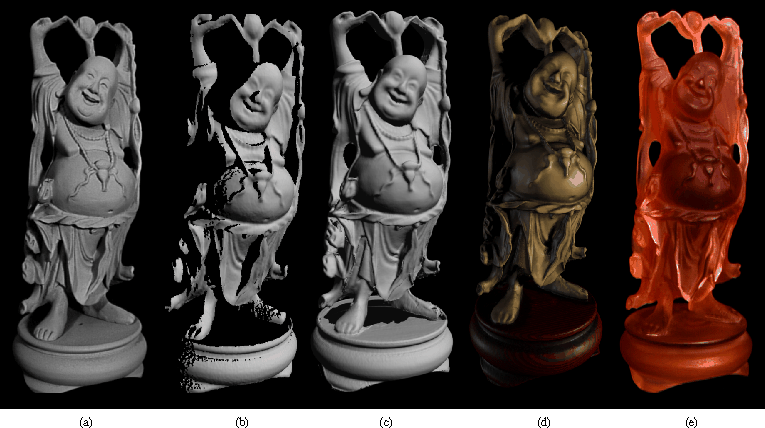
Figure 10: Reconstruction and 3D hardcopy of the ``Happy Buddha''. The original
is a plastic and rosewood statuette that stands 20 cm tall. Note that
the camera parameters for each of these images is different, creating
a slightly different perspective in each case. (a) Photograph of the
original after spray painting it matte gray to simplify scanning. (b)
Gouraud-shaded rendering of one range image of the statuette. Scans
were acquired using a Cyberware scanner, modified to permit spacetime
triangulation [6]. This figure illustrates the limited and fragmentary
nature of the information available from a single range image. (c)
Gouraud-shaded rendering of the 2.4 million polygon mesh after merging
48 scans, but before hole-filling. Notice that the reconstructed mesh
has at least as much detail as the single range image, but is less
noisy; this is most apparent around the belly. The hole in the base
of the model corresponds to regions that were not observed directly by
the range sensor. (d) RenderMan rendering of an 800,000 polygon
decimated version of the hole-filled and filtered mesh built from 58
scans. By placing a backdrop behind the model and taking 10
additional scans, we were able to see through the space between the
base and the Buddha's garments, allowing us to carve space and fill
the holes in the base. (e) Photograph of a hardcopy of the 3D model,
manufactured by 3D Systems, Inc., using stereolithography. The
computer model was sliced into 500 layers, 150 microns apart, and the
hardcopy was built up layer by layer by selectively hardening a liquid
resin. The process took about 10 hours. Afterwards, the model was
sanded and bead-blasted to remove the stair-step artifacts that arise
during layered manufacturing.
Statistics for the reconstruction of the dragon and Buddha models appear in Figure 11. With the optimizations described in the previous section, we were able to reconstruct the observed portions of the surfaces in under an hour on a 250 MHz MIPS R4400 processor. The space carving and hole filling algorithm is not completely optimized, but the execution times are still in the range of 3-5 hours, less than the time spent acquiring and registering the range images. For both models, the RMS distance between points in the original range images and points on the reconstructed surfaces is approximately 0.1 mm. This figure is roughly the same as the accuracy of the scanning technology, indicating a nearly optimal surface reconstruction.
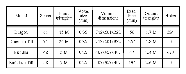
Figure 11: Statistics for the
reconstruction of the dragon and Buddha models, with and without space
carving.