The examples in this paper were acquired using a Cyberware 3030 MS laser stripe optical triangulation scanner. Figure 1b illustrates the scanning geometry: an object translates through a plane of laser light while the reflections are triangulated into depth profiles through a CCD camera positioned off axis. To improve the quality of the data, we apply the method of spacetime analysis as described in [6]. The benefits of this analysis include reduced range noise, greater immunity to reflectance changes, and less artifacts near range discontinuities.
When using traditional triangulation analysis implemented in hardware in our Cyberware scanner, the uncertainty in triangulation for our system follows the lines of sight of the expanding laser beam. When using the spacetime analysis, however, the uncertainty follows the lines of sight of the camera. The results described in section 6 of this paper were obtained with one or the other triangulation method. In each case, we adhere to the appropriate lines of sight when laying down signed distance and weight functions.
The creation of detailed, complex models requires a large amount of input data to be merged into high resolution voxel grids. The examples in the next section include models generated from as many as 70 scans containing up to 12 million input vertices with volumetric grids ranging in size up to 160 million voxels. Clearly, time and space optimizations are critical for merging this data and managing these grids.
The core data structure is a run-length encoded (RLE) volume with three run types: empty, unseen, and varying. The varying fields are stored as a stream of varying data, rather than runs of constant value. Typical memory savings vary from 10:1 to 20:1. In fact, the space required to represent one of these voxel grids is usually less than the memory required to represent the final mesh as a list of vertices and triangle indices.
Updating the volume from a range image may be likened to inverse volume rendering: instead of reading from a volume and writing to an image, we read from a range image and write to a volume. As a result, we leverage off of a successful idea from the volume rendering community: for best memory system performance, stream through the volume and the image simultaneously in scanline order [18]. In general, however, the scanlines of a range image are not aligned with the scanlines of the voxel grid, as shown in Figure 7a. By suitably resampling the range image, we obtain the desired alignment (Figure 7b). The resampling process consists of a depth rendering of the range surface using the viewing transformation specific to the lines of sight of the range sensor and using an image plane oriented to align with the voxel grid. We assign the weights as vertex ``colors'' to be linearly interpolated during the rendering step, an approach equivalent to Gouraud shading of triangle colors.
To merge the range data into the voxel grid, we stream through the voxel scanlines in order while stepping through the corresponding scanlines in the resampled range image. We map each voxel scanline to the correct portion of the range scanline as depicted in Figure 7d, and we resample the range data to yield a distance from the range surface. Using the combination rules given by equations 3 and 4, we update the run-length encoded structure. To preserve the linear memory structure of the RLE volume (and thus avoid using linked lists of runs scattered through the memory space), we read the voxel scanlines from the current volume and write the updated scanlines to a second RLE volume; i.e., we double-buffer the voxel grid. Note that depending on the scanner geometry, the mapping from voxels to range image pixels may not be linear, in which case care must be taken to resample appropriately [5].
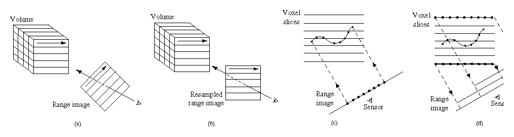
Figure 7: Range image resampling and scanline order voxel updates. (a) Range
image scanlines are not in general oriented to allow for coherently
streaming through voxel and range scanlines. (b) By resampling the
range image, we can obtain the desired range scanline orientation.
(c) Casting rays from the pixels on the range image means cutting
across scanlines of the voxel grid, resulting in poor memory
performance. (d) Instead, we run along scanlines of voxels, mapping
them to the correct positions on the resampled range image.
For the case of merging range data only in the vicinity of the surface, we try to avoid processing voxels distant from the surface. To that end, we construct a binary tree of minimum and maximum depths for every adjacent pair of resampled range image scanlines. Before processing each voxel scanline, we query the binary tree to decide which voxels, if any, are near the range surface. In this way, only relevant pieces of the scanline are processed. In a similar fashion, the space carving steps can be designed to avoid processing voxels that are not seen to be empty for a given range image. The resulting speed-ups from the binary tree are typically a factor of 15 without carving, and a factor of 5 with carving. We did not implement a brute-force volume update method, however we would expect the overall algorithm described here would be much faster by comparison.
To generate our final surfaces, we employ a Marching Cubes algorithm [20] with a lookup table that resolves ambiguous cases [22]. To reduce computational costs, we only process voxels that have varying data or are at the boundary between empty and unseen.