Each pixel contains four 8bit values, Alpha, Blue, Green, and Red. Modifing or analizing the video data constited of simply of advancing to the correct position in the data and reading in the ABGR values.
With the camera code obtained and with a good understanding of the format of video data, we began to manipulate the video data to do some simple filtering. Our primary concern at this point was to test the speed of a simple filter writen in C on the video data.
The first test of the video code was the a simple threshold filter defined by the following pesudo code:
The results of the filtering were quite impressive. The refresh on the camera was fast enough such that latency did not seem to be an immediate concern.
Following the sucess of the image filtering, we wanted to see if we could write a simple filter that showed a moving object such as a hand. This was done by using the first frame of the video data as a background image to which following frames are subtracted. Using the same threshold filter with the new additional background filter, the results were promising. By placing an object, including a hand, in front of the camera, the filter picked up only that object.
Once we had a working filter which identified where an object was in the viewplane, it was simple task to compute the posistion of the object. By taking each pixel of the object and averaging the x and y coordinates for each frame, the position could be obtained. We modified our filtering program to print out the position of the object. The following data set was constructed by moving a flashlight around the screen.

181, 94
177, 94 175, 94 171, 94 162, 92 155, 93 149, 94 141, 93 135, 91 128, 90 124, 90 119, 92 113, 91 109, 92 104, 92 98, 91 94, 90 89, 91We were still using the basic threshold filtering for determining the object's position and we were quick to realize that it would not be a usable filtering method for determining hand position. The first problem was that it performed a background subtraction to remove bright objects that the camera should ignore. Although this did what it was supposed to do, the user could not enter anything but the hand into the field of view of the camera. If the users face for example entered the picture, it would get registered in the filtering. Also, moving the hand in front of bright spots in the background caused that portion of the hand not to get noticed by the filtering.
To solve these problems we worked on different image filtering algorthms that were based on the color information that the camera was providing rather than relying on background subtraction. What we hoped to have was for the user to wear a colored glove which the filtering would be able to recognize. In the end, wedid not need a glove.
Since we didn't have any brightly colored gloves in the lab, we decided to try and write a color sentive filter by picking up only redish pixels because the only thing we could find was a empty Coke bottle (which is featured in our Interactive Room). The filter was designed such that it marked pixels that had a red component above a threshold and a green and blue value below 255 - treshold. This did work well for picking up red however it was highly senitive to the brightness of the image so as the Coke bottle moved away from the camera and light source, the filtering began to fail. To solve this problem, we treated the RGB values as color vector and normalized it. This eliminated any concerns about pixel brightness. Since we didn't want to perform a square root for each pixel, we used the sum of the RGB values as an estimation of the vector length. The resulting code was run on each pixel:
- static int TEST (char *R, char *G, char *B, int threshold) {
- int itot = *R + *G + *B;
- if (itot > threshold && (int)(*R) * 255 / itot > threshold &&
- int itot = *R + *G + *B;
- (int)(*G) * 255 / itot < 255 - threshold &&
- (int)(*B) * 255 / itot < 255 - threshold) {
- return 1;
- }
- return 1;
- return 0;
- }
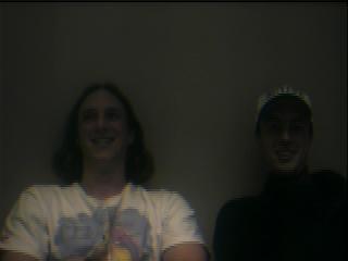
 This is the input recieved from the camera.
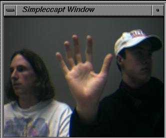
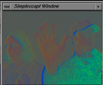 This is what TEST compares when looking for red in the image. Each pixel
is an approximate normalization of the RGB values.
This is what TEST compares when looking for red in the image. Each pixel
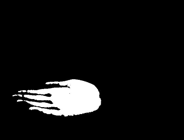
is an approximate normalization of the RGB values.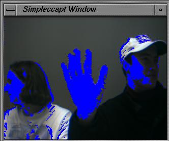 The results of the threshold test are colored blue for indicating where
the TEST found "red" pixels. The first thing that we noticed about the algorith
is that it can pick up resonably lit flesh tones very well. See that the
white of the hand is not colored, but the hand is completly colored in blue.
By averging the blue pixels the position of the hand can be noted. This
method does not elimnate the problem of having the users face in the picture,but
if the threshold value is set correctly for the camera it is possible for
the filter to ignore the face. With a working camera recognition program,
we were ready to expand the system to work in three dimentions by triangulating
two camera inputs.
The results of the threshold test are colored blue for indicating where
the TEST found "red" pixels. The first thing that we noticed about the algorith
is that it can pick up resonably lit flesh tones very well. See that the
white of the hand is not colored, but the hand is completly colored in blue.
By averging the blue pixels the position of the hand can be noted. This
method does not elimnate the problem of having the users face in the picture,but
if the threshold value is set correctly for the camera it is possible for
the filter to ignore the face. With a working camera recognition program,
we were ready to expand the system to work in three dimentions by triangulating
two camera inputs.Socket Connections
Before introducing a new camera into the system, we needed construct a simple client/server socket system. This was writen to allow the passing of vector data over a socket connection. Our socket drivers currently support the passing of three or four dimentional vector information between a client and server. This was entirely done in C++. (See sockets.h and sockets.cc)
Connecting Two Cameras & Triangulation:
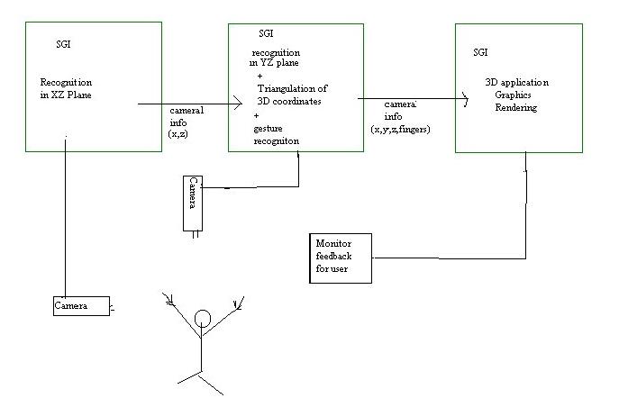
After the socket drivers and camera filters were completed, we needed to combine to camera inputs into a three dimentional vector representing the hand position in three space. Originally, this was our network diagram.

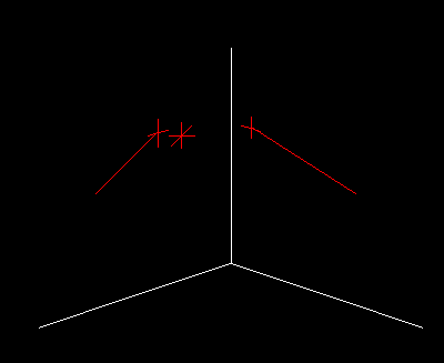
Two Indigos were responsible for filtering their camera data to produce a two dimentional vector which represented the hand position according to that camera's viewplane. The server receieved this data and was responsible for figuring out the 3D position of the hand. Assuming the camera are at right angles to each other, the triangulation was done by projecting the ray originating from one camera to the point in the viewplane, onto the plane defined by the ray originating from the second camera. Here is the output of a sample appilication that we used to test the triangulation.
The only difficulty we had with the triangulation algoithem is that is requires the cameras to be at right angles of each other. Although the triangulation still works when they are off center, the accuracy becomes very poor.
We created a program called Fishing. This was modled after a similar to the one shown in a HCI lecture given by Dr. Zhai. The objective was to create a program in which users could learn our input device. Also this was our first real test of the accuracy of the device. The performance was satifactory. We noticed that the fishing application was only using about every thrid vector it recieved from the camera sockets. This led us to the conclusion that one of the SGIs responsible for the camera recognition could do more work. We redesigned our Network flow so that One of the Camera SGI's was responsible for finding the 3D position. The new network flow is shown in the following diagram:
New Block Diagram
After celebrating, we began to implement the interactive room. We soon realized that we would require addition imputs to control the items in the room. This was acomplished by implementing a simple form of gesture recognition which determined how many fingers the user was holding up. At first we had no idea how we would figure out the number fingers the user had up. We thought of such ways as complicated statistical search algorithms. Then we said Duh and came up with a scan line algorithm. Origonally, we performed a scan line test which scaned horizontal lines for patches of hand color. This however proved to be ineffective for most frames and could not recognize a closed fist at all. The solution was to scan an arch relative to the hand position. The following image demonstrates how this was done.
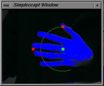 The filter algorithm scans to the top and left of the hand. It then computes
an arch which covers the fingers. Scaning this arch provides accurate finger
information. We orgionally had the algorithm assume that the hand was upright
however this proved to be quite uncomfortable so we now assume the hand
is sideways. This seem to work well for the conditions provided in the ICGL
lab. Note: this can be modified for other work enviroments. Also, the hand
must be oriented facing the second camera.
The filter algorithm scans to the top and left of the hand. It then computes
an arch which covers the fingers. Scaning this arch provides accurate finger
information. We orgionally had the algorithm assume that the hand was upright
however this proved to be quite uncomfortable so we now assume the hand
is sideways. This seem to work well for the conditions provided in the ICGL
lab. Note: this can be modified for other work enviroments. Also, the hand
must be oriented facing the second camera.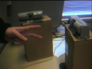
To demonstrate our new guesture recognigion, we created a simple sound player application called Fingers which played different sounds depending on the number or fingers held up.
To be brown nosers, we decided to try to create a Theramin using our input device, called Theraflu. We modified some SGI code that outputed a sin wave to the audio hardware. This worked well but it was clicky. The period would became messed up with every loop. We found it easier to work with a saw-tooth wave. This produced a much smoother sound. Our final program was still not very good compared to the theramin. One thing that is noticably different is the affects of finger movement. Because finger movement does not move the hand position very much in our program, finger movement does not have the cool affects that it does on the real theramin.
We created an interactive room to try to tie everything our input device can do together. In this room, the user can turn things on/off and pickup/drag/drop items. The room worked satisfactorily under the ICGL condtions. Sometimes it was a little hard to control the room. We found that making the objects big and limiting the number objects helps keep confusion to a minimum.
Our original plan was to hook this device up to our CS426 final project. For a while we did not think we would actually get to it. We were impressed with how easy it was to hook this up to VRMUD modeling, a project that has progessed independantly of this HCI project. Vrmud Modeling is still in development so we have only seen some of the results that this input device has provided. We are convinced that it will be very useful.
Things that would make our project better.
- }
- We really need a controlled environment. people lights and flesh colored wall tend to interfere with our recognition. Ideally we would like a black room, with a person wearing a black suit, with our own lights.
- Another thing that would be really useful is if we could get longer camera cords. Because the cameras cannot be very far apart the work space is limited. This makes small movements in your hand very sensitive.
- Faster machines
- Better cameras. The ones we are using do not pick up colors very well and
there is a lot of variation between different cameras.
Special Thanks:
Tom Sanocki: who wrote the socket drivers and is working on the Mud modeling
Rob Jensen: for answering all of our questions about Inventor.